Method for improving thermal conversion efficiency of air conditioning evaporator

A technology of heat conversion and evaporator, applied in evaporator/condenser, heat exchange equipment, water shower cooler, etc., can solve the problem of low comprehensive heat absorption capacity of evaporator, poor evaporation heat absorption effect, and low water mist evaporation efficiency and other issues, to achieve the effect of improving the comprehensive evaporation and heat absorption efficiency, improving the cooling efficiency, and increasing the evaporation rate of water mist

Active Publication Date: 2018-08-24
深圳市企富晟科技有限公司
View PDF5 Cites 2 Cited by
  • Summary
  • Abstract
  • Description
  • Claims
  • Application Information

AI Technical Summary

Problems solved by technology

[0004] The position of the existing evaporator is relatively fixed. Because the hot air density is lighter and located on the upper layer, the mist attached to the evaporator fins is easier to evaporate, and its cooling efficiency is higher; the corresponding bottom layer is cooler air, causing the bottom to evaporate. The thermal effect is poor; at the same time, as the depth of the air penetrating into the evaporator gradually increases, the temperature gradually decreases, which makes the internal water mist evaporation efficiency also low, making the comprehensive heat absorption capacity of the evaporator low

Method used


Image

  • Method for improving thermal conversion efficiency of air conditioning evaporator
  • Method for improving thermal conversion efficiency of air conditioning evaporator
  • Method for improving thermal conversion efficiency of air conditioning evaporator

Examples


Embodiment Construction

[0030] In order to make the technical means, creative features, goals and effects achieved by the present invention easy to understand, the present invention will be further described below in conjunction with specific embodiments.

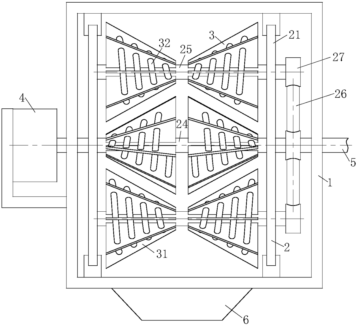
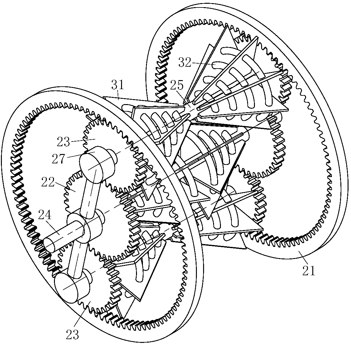
[0031] Such as Figure 1 to Figure 6 As shown, a method for improving the heat conversion efficiency of an air-conditioning evaporator according to the present invention, the method for improving the heat conversion efficiency includes the following steps:

[0032] Step 1, the end of the output shaft of the reducer 4 is fixedly connected to the sun gear shaft 24 through a coupling; the sun gear shaft 24 is rotatably connected to the housing 1 through a bearing; the other end of the sun gear shaft 24 is rotatably connected to the input shaft. Water pipe 5, the water inlet pipe 5 is used to input pressure water flow to the evaporation unit 3 through the sun gear shaft 24; the evaporation unit 3 is arranged in the middle of the sun gear shaft 24; Fo...


PUM


Abstract

The invention belongs to the technical field of air conditioning evaporators, and particularly provides a method for improving the thermal conversion efficiency of an air conditioning evaporator. A sun gear shaft is rotationally connected with a shell through a bearing. One end of the sun gear shaft is fixedly connected with an output shaft of a speed reducer through a coupler, the other end of the sun gear shaft is rotationally connected with a water inflow pipe, and the water inflow pipe is used for inputting pressure currents to evaporation units through the sun gear shaft. The evaporationunits are arranged in the middle of the sun gear shaft. The evaporation units spray out water mist through conical spiral pipes to be used for evaporative heat absorption. Sun gears are arranged at the two ends of the sun gear shaft. Planet gears are arranged in cooperation with the sun gears, and rotating modules are formed. The rotating modules are used for balancing the evaporation rates of theevaporation units at different positions. Sealing units are arranged at the joint of a connecting pipe and a planet gear shaft. The method is especially suitable for large water-cooled air conditioning units, the evaporation efficiency of the top, the bottom, the exterior and the interior of the evaporator reaches a balanced state, and the refrigerating efficiency of an air conditioner is improved.

Description

technical field [0001] The invention belongs to the technical field of air-conditioning evaporators, and specifically relates to a method for improving the heat conversion efficiency of an air-conditioning evaporator. Background technique [0002] In addition to the cooling function, the water-cooled air conditioner also has the functions of ventilation, dust removal, and deodorization. It is the most commonly used ventilation and cooling equipment in enterprise workshops, public places, commercial and entertainment places, etc. [0003] The water-cooled air conditioner utilizes the physical property of absorbing the surrounding heat during the evaporation of water vapor. The water-cooled air conditioner is equipped with an evaporator at the air inlet. When the air passes through the evaporator, heat is absorbed and the temperature drops by 5-8°C. The cooled air is sent into the room through the air supply duct of the water-cooled air conditioner to reduce the indoor tempe...

Claims


Application Information

Patent Timeline
IPC IPC(8): F25B39/02F28D11/04F28F25/06
CPCF25B39/02F25B39/028F28D11/04F28F25/06F28F2230/00
Inventor 张帝何东旭田良奇
Owner 深圳市企富晟科技有限公司
Why Eureka
Try Eureka