
Dimming circuit, dimming device and dimming control method

A technology of dimming circuit and dimming controller, which is applied in the field of dimming device, dimming control and dimming circuit, and can solve the problems of easy failure, flexible brightness adjustment, large output voltage, etc.

Pending Publication Date: 2018-08-21
WENZHOU MTLC ELECTRIC APPLIANCES
View PDF0 Cites 0 Cited by
  • Summary
  • Abstract
  • Description
  • Claims
  • Application Information

AI Technical Summary

Problems solved by technology

[0003] At present, traditional dimming methods usually directly use adjustable loads for dimming. For example, the most common ones are LED sensor lights or infrared sensor lights. The brightness signal realizes that the light is always on or off, or the light is turned on when people come and go off according to the infrared signal, so it is impossible to flexibly adjust the light according to human needs
It can be seen that the traditional dimming method requires real-time detection, so the lighting circuit needs to work for a long time. Obviously, its output voltage is relatively large, that is, if the induction lamp or infrared induction lamp is always in the working state, it is easy to break down and affect its service life.

Method used


Image

  • Dimming circuit, dimming device and dimming control method
  • Dimming circuit, dimming device and dimming control method
  • Dimming circuit, dimming device and dimming control method

Examples


Embodiment 1

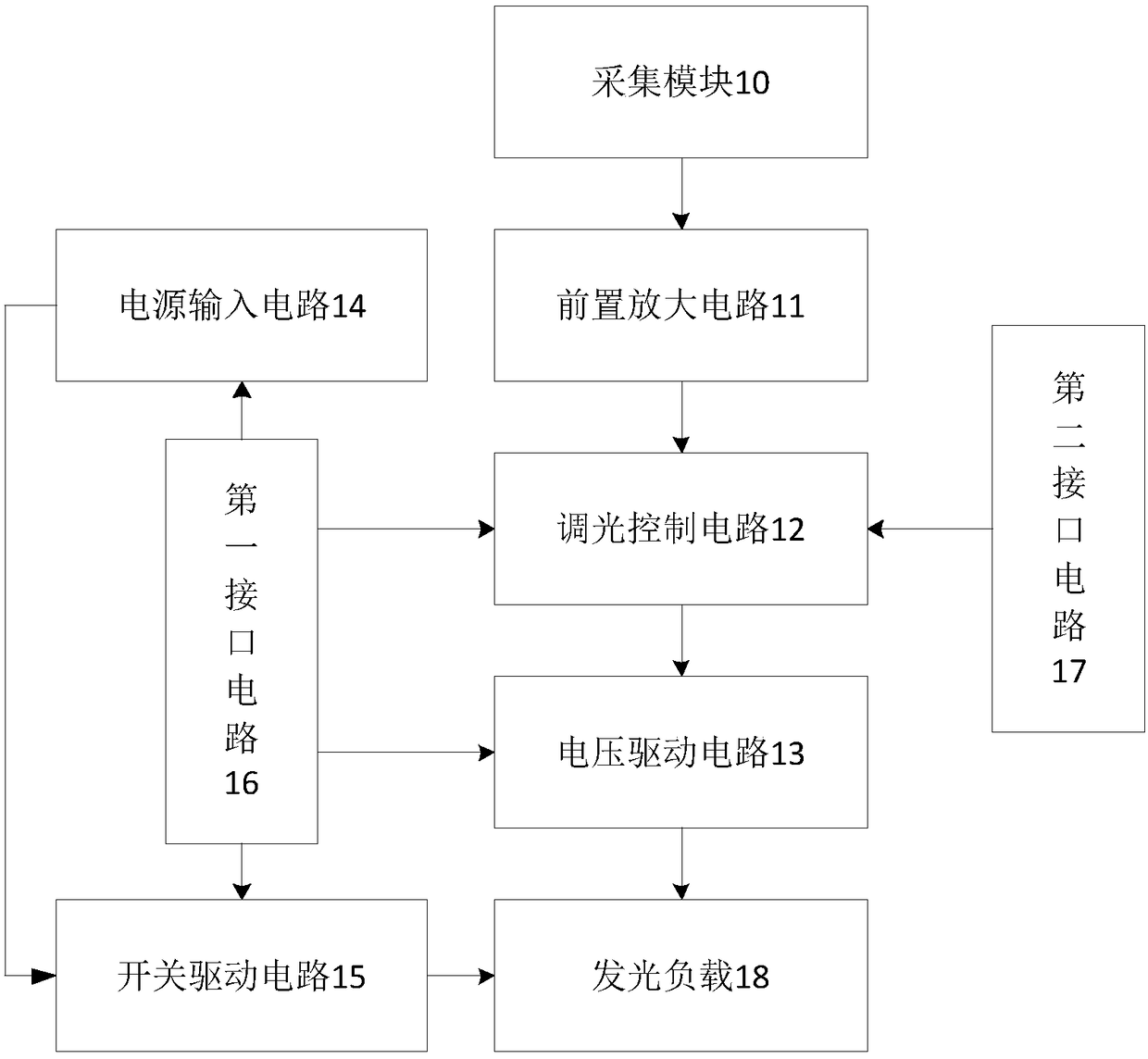
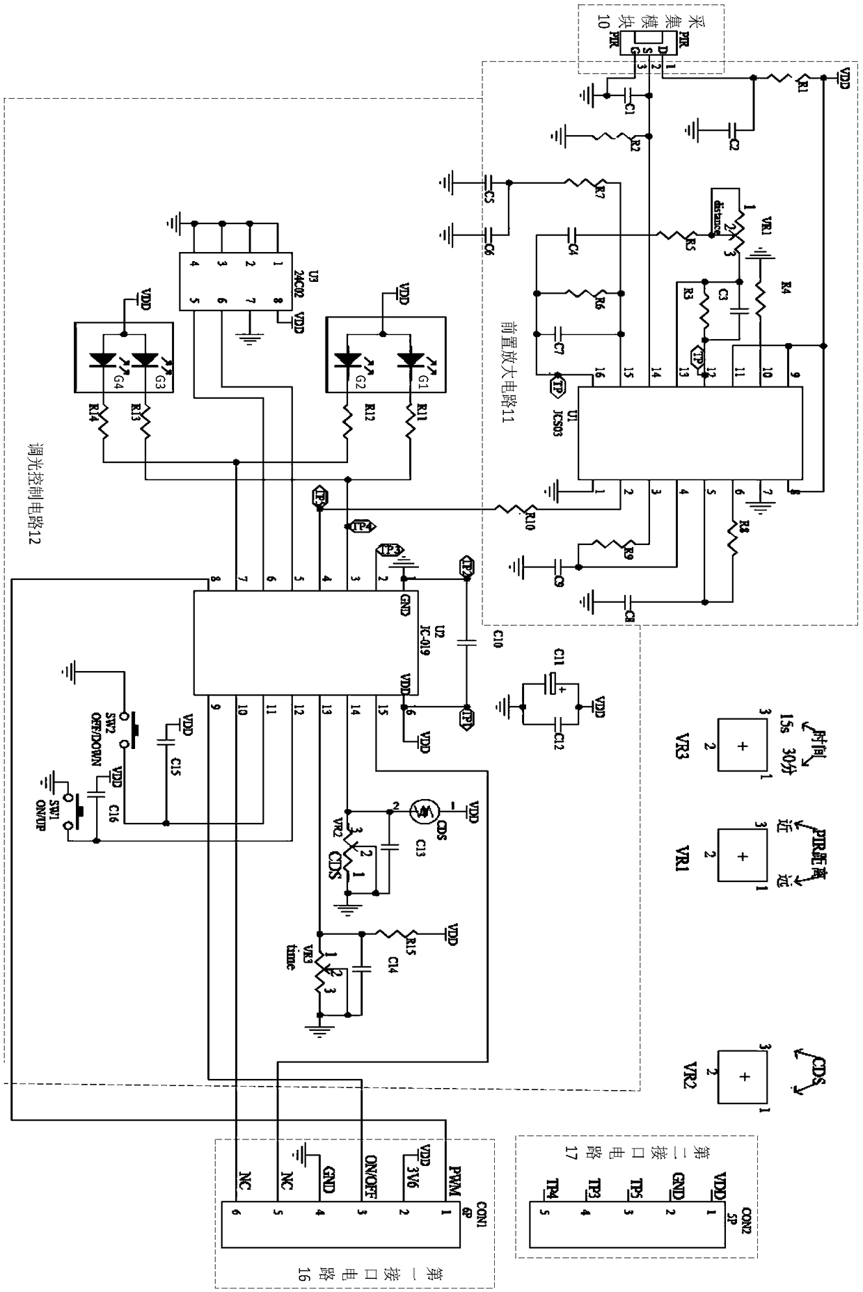
[0068] An embodiment of the present invention provides a dimming circuit, such as figure 1 As shown, it includes: an acquisition module 10 , a preamplifier circuit 11 , a dimming control circuit 12 and a voltage drive circuit 13 . The dimming circuit can adjust the brightness and darkness of the light-emitting load 18 to meet environmental requirements and human requirements, so it brings convenience to people's life and adds fun to people's life. For example: Various places require LED lights to show colorful light and dark changes in the night scene, and this colorful light and dark change comes from the dimming circuit. The dimming circuit in the embodiment of the present invention can also meet individual needs based on the dimming basis. For example, everyone has different eyesight and has different perceptions of the same light, and can realize different degrees of brightness of LED lights through the dimming circuit according to individual needs. Dark change.

[0069]...

Embodiment 2

[0086]An embodiment of the present invention provides a dimming device, which includes a housing and a wiring board arranged inside the housing, and the wiring board is provided with the dimming circuit in the embodiment. The dimming circuit includes an acquisition module 10 , a preamplifier circuit 11 , a dimming control circuit 12 , a voltage drive circuit 13 , a power input circuit 14 , a switch drive circuit 15 , a first interface circuit 16 and a second interface circuit 17 . The dimming device can be connected to the light-emitting load 18, and then assist the light-emitting load 18 to perform dimming, to meet the personal needs of users, flexibly adjust the brightness of the light-emitting load 18, and make it output a more ideal voltage parameter, thereby enhancing the service life of the light-emitting load 18 , bringing great convenience to users.

Embodiment 3

[0088] An embodiment of the present invention provides a dimming control method, which is used in the dimming circuit in Embodiment 1, such as Figure 7 As shown, the dimming control method in this embodiment includes:

[0089] S71. Acquire a voltage sensing parameter corresponding to the sensing signal amplified by the preamplifier circuit, a first preset voltage threshold, and a second preset voltage threshold. The first preset voltage threshold here is a specific value, and the second preset voltage threshold is a range value, for example: the first preset voltage threshold is 3V, the second preset voltage threshold is (0V, 10V], the induction The signal is a voltage signal collected by the collection module.

[0090] S72. Comparing the voltage sensing parameter with a first preset voltage threshold to obtain a voltage comparison result. For example, if the voltage sensing parameter is 3.6V, it is compared with a preset voltage threshold of 3V to obtain 3.6V>3V, which cor...


PUM


Abstract

The invention discloses a dimming circuit, a dimming device and a dimming control method. The dimming circuit comprises a collecting module used for collecting inductive signals, a pre-amplification circuit connected with the collecting module and used for conducting pre-amplification on the inductive signals, a dimming control circuit connected with the pre-amplification circuit and used for generating voltage parameters for driving a luminous load according to the amplified inductive signals, and a voltage driving circuit connected with the dimming control circuit and used for driving the luminous load according to the voltage parameters. By means of the dimming circuit, the dimming device and the dimming control method, flexible dimming can be conducted according to users' individual requirements and environmental requirements, so ideal voltage parameters are output, and great convenience is brought to users; meanwhile, it can be avoided that the luminous load works continuously, then it is avoided that the output voltage of the luminous load is too high, and thus the service life of the luminous load can be prolonged.

Description

technical field [0001] The invention relates to the technical field of dimming circuits, in particular to a dimming circuit, a dimming device and a dimming control method. Background technique [0002] In LED lighting fixtures, infrared sensing technology is usually used to perceive environmental information to realize dimming, temperature adjustment or color adjustment of LED lights. Infrared sensor is a common sensor used for automatic control of lamps, usually used in corridors, Corridors, bathrooms, garages and other places are supplemented by LED lights for lighting, so that the LED lights can be turned on when people come and go off when people leave. [0003] At present, traditional dimming methods usually directly use adjustable loads for dimming. For example, the most common ones are LED sensor lights or infrared sensor lights. The brightness signal realizes that the light is always on or off, or according to the infrared signal, the light is on when people come an...

Claims


Application Information

Patent Timeline
IPC IPC(8): H05B33/08H05B44/00
CPCH05B45/10
Inventor 高伟
Owner WENZHOU MTLC ELECTRIC APPLIANCES
Learn More