
Electric vehicle charging pile

A technology of electric vehicles and charging piles, which is applied in the direction of electric vehicle charging technology, electric vehicles, charging stations, etc., can solve the problems of charging gun leakage, rainwater falling obliquely, and easy to hit the opening of the side wall directly, so as to avoid short circuit , The way of placing is simple, and the effect of pulling the rope is stable

Active Publication Date: 2018-08-21
思极星能科技(四川)有限公司
View PDF6 Cites 3 Cited by
  • Summary
  • Abstract
  • Description
  • Claims
  • Application Information

AI Technical Summary

Problems solved by technology

[0002] Electric vehicles are favored by many users because of their low electricity cost and strong environmental protection. However, because electric vehicles need to be charged at a voltage of 380 volts, they cannot use the daily household power supply, and additional charging piles are required to charge the vehicles.
[0003] Chinese patent CN104836298B discloses a waterproof charging pile for electric vehicles. In this document, the box body is arranged on the side wall of the charging pile, and the inlet of the charging gun is arranged in a horizontal direction, which has efficient waterproof performance; but in actual use During the process, due to the action of the wind, the rainwater will fall obliquely, and it is easy to hit the opening of the side wall directly. Once the amount of rainwater is large, it is easy to cause part of the water to penetrate into the box, causing the charging gun to leak, short circuit, etc.

Method used


Image

  • Electric vehicle charging pile
  • Electric vehicle charging pile
  • Electric vehicle charging pile

Examples


Embodiment Construction

[0027] In order to enable those skilled in the art to better understand the solutions of the present invention, the technical solutions in the embodiments of the present invention will be clearly and completely described below in conjunction with the drawings in the embodiments of the present invention.

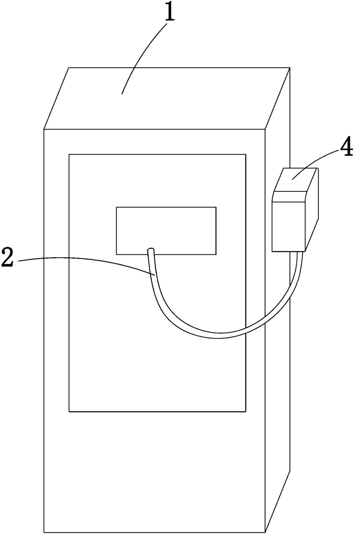
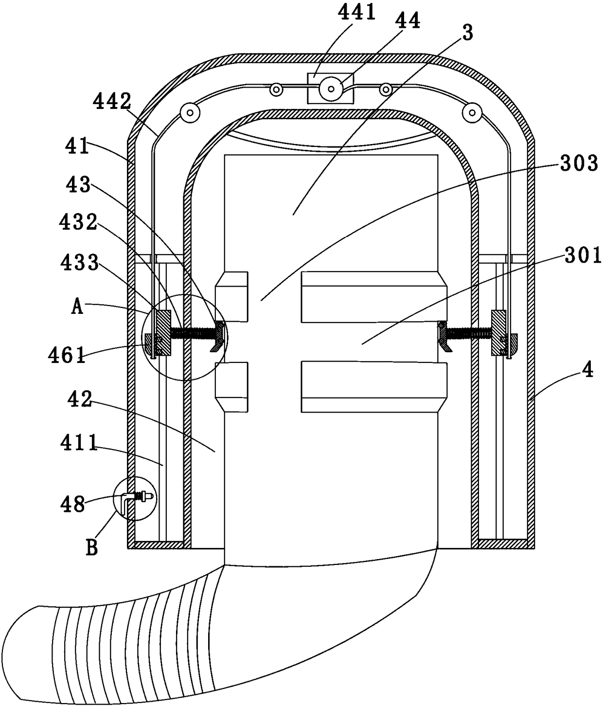
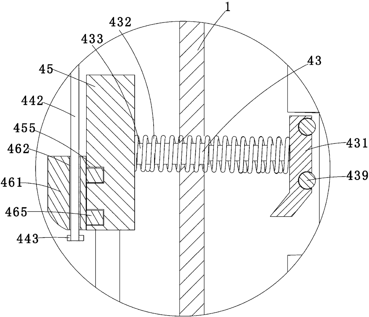
[0028] Such as Figure 1-6 As shown, an electric vehicle charging pile includes a charging pile body 1, an electric wire 2, a charging gun 3 and a placement device 4, wherein the charging pile body 1 is an existing charging pile on the market, and the charging pile body 1 is connected to 380V power supply, which is the prior art, will not be repeated here; the wire 2 is a wire with a copper core, the wire 2 is connected to the charging pile body 1, and the charging gun 3 is connected to the wire 2. When in use, the charging gun 3 is connected to the charging hole of the electric vehicle, and the end of the charging gun 3 is inserted into the charging hole, so as to realize th...


PUM


Abstract

The invention discloses an electric vehicle charging pile comprising a charging pile body which is arranged on the ground or a wall, a wire for transmitting a current through the charging pile, a charging gun connected with one end of the wire and used for being inserted in a vehicle charging hole and a placing device for placing the charging gun, wherein the placing device includes a box body, aplacing chamber with a downward opening, a clamping component disposed in the placing chamber and a driving component for driving the clamping component to move upwards. The clamping component is matched with the charging gun to clamp the charging gun. The opening of the placing chamber is arranged to be downward. When falling to the box body, rainwater flows down along the left side and the rightside wall of the box body and does not permeate into the placing chamber during flowing, so that the placing chamber is internally continuously kept dry, it is ensured that the charging gun is not affected by moisture, and the short circuit and electric leakage and the like of the charging gun are effectively avoided.

Description

technical field [0001] The invention belongs to the technical field of electric vehicles, in particular to an electric vehicle charging pile. Background technique [0002] Electric vehicles are favored by many users because of their low electricity cost and strong environmental protection. However, because electric vehicles need to be charged at a voltage of 380 volts, they cannot use the daily household power supply, and additional charging piles are required to charge the vehicles. . [0003] Chinese patent CN104836298B discloses a waterproof charging pile for electric vehicles. In this document, the box body is arranged on the side wall of the charging pile, and the inlet of the charging gun is arranged in a horizontal direction, which has efficient waterproof performance; but in actual use During the process, due to the action of the wind, the rainwater will fall obliquely, and it is easy to hit the opening of the side wall directly. Once the amount of rainwater is larg...

Claims


Application Information

Patent Timeline
Patent Type & Authority Applications(China)
IPC IPC(8): B60L11/18
CPCB60L53/31Y02T10/70Y02T10/7072Y02T90/12
Inventor 刘子新李文婷陈怡君
Owner 思极星能科技(四川)有限公司
Learn More