Handheld fluorescent image navigation positioning device

A navigation and positioning, hand-held technology, applied in the field of medical imaging, can solve the problems that the imaging optical path and the projection optical path cannot be focused at the same time, the projection pattern cannot be accurately registered, and the operation is inconvenient, so as to avoid unclear boundaries of tumor tissues, Easy to promote and use, display intuitive effects

Pending Publication Date: 2018-08-21
UNIV OF SCI & TECH OF CHINA
View PDF2 Cites 6 Cited by
  • Summary
  • Abstract
  • Description
  • Claims
  • Application Information

AI Technical Summary

Problems solved by technology

Among them, the common optical axis imaging projection navigation device adopts the common optical axis design of image acquisition and projection. Such a design cannot achieve simultaneous focusing of the imaging optical path and projection optical path, or can only achieve clear focus of the acquisition and projection images by focusing separately. , Relying on the recognition with the naked eye brings projection errors and consumes a lot of operation time
And in order to ensure the coaxial system, the optical path of these coaxial systems is complicated, and most of them are large desktop products, which are inconvenient to use and operate.
[0006] In order to solve the above-mentioned clinical problems, some surgical projection navigation devices designed with parallel optical axes have been developed, such as the Chinese patent "a breast cancer imaging projection navigation system" (patent application number: 201420339875.X) and "a A Projection Navigation Device for Imaging Lesions” (patent application number: 201510068823.2). This type of projection navigation device parallel to the optical axis has a simple optical path, small device size, and high fluorescence efficiency. However, when the working distance of the device changes, the projection pattern cannot Real-time accurate registration with real biological tissue, the base design also has certain limitations on the doctor's operation

Method used


Image

  • Handheld fluorescent image navigation positioning device

Examples


Embodiment Construction

[0022] The present invention will be further described below in conjunction with the accompanying drawings and specific embodiments.

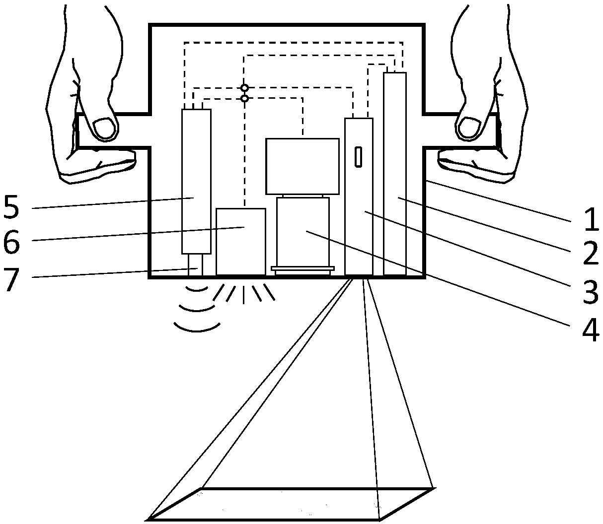
[0023] refer to figure 1 As shown, the present invention provides a handheld fluorescent image navigation and positioning device. The handheld fluorescent image navigation and positioning device includes a handheld housing 1, a power supply module 2 and an image processing module 5 located inside the handheld housing, a miniature projection module 3 located at the bottom window of the handheld housing, and an image acquisition module. 4. Excite the light source module 6 and the ranging module 7 .

[0024] The image processing module 5 is connected to the ranging module 7, the image acquisition module 4, the micro projection module 3 and the power module 2 respectively, and the power module is connected to the micro projection module 3, the excitation light source module 6 and the image processing module 5 to supply power. The excitation light...


PUM


Abstract

The invention discloses a handheld fluorescent image navigation positioning device which comprises a handheld shell (1), a power module (2), a micro-projection module (3), an image acquisition module(4), an image processing module (5), an excitation light source module (6) and a distance measuring module (7). According to the device, pathological tissues are developed by the aid of a near-infrared fluorescent imaging technique, ICG (indocyanine green) serves as a contrast medium, acquired fluorescence images directly project to corresponding diseased regions by a real-time projection mode, and projection positions and projection sizes are calibrated by the distance measuring module in real time. Compared with an existing development mode, fluorescent images of the tissues can be more visually observed, the device has higher fluorescent efficiency and better dynamic properties, the whole device is highly integrated as a handheld device, and the device is convenient to operate, can be used for clinical operation and has a good practical prospect.

Description

technical field [0001] The invention relates to the technical field of medical imaging and medical equipment, in particular to a hand-held fluorescent image navigation and positioning device. Background technique [0002] At present, due to the limitation of surgical equipment, equipment and technology, traditional medical surgery relies heavily on the clinical experience of doctors, which not only increases the work intensity of doctors, but also causes relatively large randomness in the accuracy and success rate of surgery. [0003] With the development and innovation of medical imaging technology, image processing technology and other technologies, in recent years, surgical operations are developing in the direction of precision, accuracy and speed. The surgical navigation system is a new type of surgical auxiliary equipment developed during this process. The basic principle of this type of equipment is to process medical images such as PET, CT, MRI, and fluorescence (suc...

Claims


Application Information

Patent Timeline
IPC IPC(8): A61B34/20
CPCA61B34/20A61B2034/2055A61B2034/2065
Inventor 邵鹏飞李晨梦李英锐
Owner UNIV OF SCI & TECH OF CHINA
Why Eureka
Try Eureka