Shaft structure and electronic equipment

A technology of a rotating shaft structure and electronic equipment, which is applied in the electronic field and can solve the problems of the rotatable angle, the complex structure of the rotating shaft, and the large volume.

Active Publication Date: 2021-05-18
LENOVO (BEIJING) LTD
View PDF11 Cites 0 Cited by
  • Summary
  • Abstract
  • Description
  • Claims
  • Application Information

AI Technical Summary

Problems solved by technology

[0003] In view of this, the embodiment of the present invention expects to provide a rotating shaft structure and electronic equipment, at least partially solving the above-mentioned contradiction between the rotatable angle and the complex or bulky rotating shaft structure

Method used


Image

  • Shaft structure and electronic equipment
  • Shaft structure and electronic equipment
  • Shaft structure and electronic equipment

Examples


Embodiment Construction

[0038]The technical solutions of the present invention will be further described in detail below with reference to the accompanying drawings and specific embodiments.

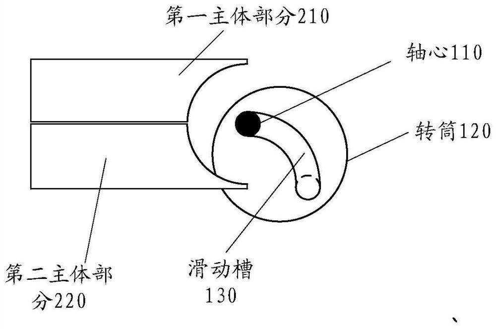
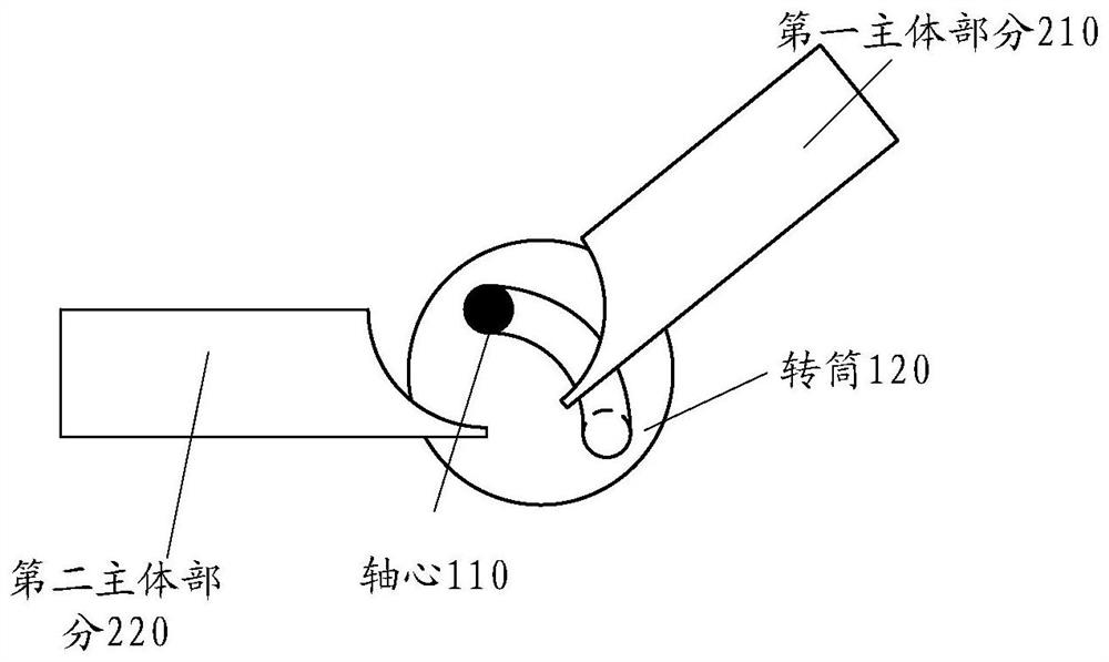
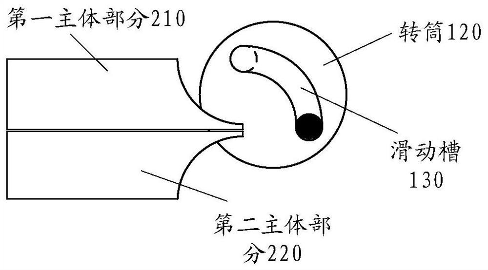
[0039]Such asFigure 1 to 4 The structure shown is a structure of an electronic device,Figure 1 to 4 There is a shaft structure,Figure 5 A side number of side numbers for special shaft structures. As described above, this embodiment provides a shaft structure, including:

[0040]Axis 110;

[0041]The drum 120 is located periphery of the axial core 110, which is capable of rotating relative to the axial center 110;

[0042]Wherein, the drum 120 is provided with a slide groove 130 for change the position of the axial core 110; the slider 130 includes a first end and a second end;

[0043]When the axial core 110 is located at the first end, the drum 120 can rotate from the first position to the second position relative to the axial core 110;

[0044]When the axial core 110 is located at the second end, the drum 120 can rotate from the sec...


PUM


Abstract

The embodiment of the invention discloses a rotating shaft structure and electronic equipment. The rotating shaft structure includes: an axis; a rotating cylinder, located on the periphery of the axis, capable of rotating relative to the axis; wherein, a sliding groove for changing the position of the axis is provided in the rotating cylinder; the The sliding slot includes: a first end and a second end; when the axis is located at the first end, the drum can rotate from the first position to the second position relative to the axis; when the axis When the center is located at the second end, the drum can rotate from the second position to the third position relative to the axis.

Description

Technical field[0001]The present invention relates to the field of electronic technology, and more particularly to a shaft structure and an electronic device.Background technique[0002]The shaft structure is typically a rotating member connected to two relative rotating portions. There are general applications in various electronic devices such as notebook or tablet. In the prior art, the rotational angle applied to the common rotating shaft structure of the electronic device is usually not more than 180 degrees, and some can achieve rotation of 360 degrees, but these rotating shaft structures may need to use a combination of multiple rotations, general structures Complex and larger shafts are large.Inventive content[0003]In view of this, the embodiment of the present invention is desirable to provide a rotating shaft structure and an electronic device, at least partially solve the problem of contradiction between the above-mentioned rotatable angle and the shaft structure.[0004]In o...

Claims


Application Information

Patent Timeline
Patent Type & Authority Patents(China)
IPC IPC(8): G06F1/16
CPCG06F1/1615G06F1/1681
Inventor 王顶宇
Owner LENOVO (BEIJING) LTD
Why Eureka
Try Eureka