Quasi-zero stiffness vibration isolator floating slab track bed and design method thereof
A quasi-zero stiffness, vibration isolator technology, applied in the field of rail vibration reduction and noise reduction, can solve problems such as no specific application examples, and achieve the effects of good low-frequency vibration isolation, small deformation capacity, and low vibration isolation starting frequency.
- Summary
- Abstract
- Description
- Claims
- Application Information
AI Technical Summary
Problems solved by technology
Method used
Image
Examples
Embodiment 1
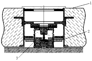
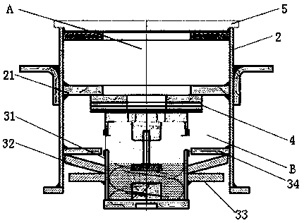
[0037] The quasi-zero stiffness vibration isolator floating slab track bed is characterized in that it includes a floating slab 1 and a vibration isolation assembly arranged in the floating slab 1, and the vibration isolation assemblies are distributed along the length direction of the floating slab 1 at intervals, and is characterized in that the The vibration isolation assembly includes the outer sleeve 2 poured in the floating plate 1 and the quasi-zero stiffness vibration isolator 3 installed in the outer sleeve 2, and the quasi-zero stiffness vibration isolator 3 and the outer sleeve 2 are cushioned There are height-adjusting spacers 4 for adjusting the height of the floating plate 1, and the top of the outer sleeve 2 is covered with an insulating cover plate 5.
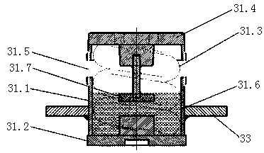
[0038] The quasi-zero-stiffness vibration isolator 3 includes a linear positive-stiffness elastic element and a negative-stiffness elastic element connected in parallel with the linear positive-stiffness elastic ...
Embodiment 2
[0045] The difference from Embodiment 1 lies in the installation position of the Belleville spring. In this embodiment, the Belleville spring is installed in the installation cavity A, such as Figure 4 As shown, the outer wall of the steel spring vibration isolator 31 is welded with an annular disc spring support seat 35, and the disc spring support seat 35 is arranged in the axial direction, passes through the support baffle plate 21, and penetrates into the installation chamber In A, the disc spring 32 is installed in the installation chamber A, and is arranged to flare downwards. The top of the disc spring 32 abuts against the insulating cover plate 5 , and the bottom of the disc spring 32 abuts against the disc spring support seat 35 .
[0046] The bottom surface of the insulating cover plate 5 is fixed with a T-shaped mounting seat 36 that matches the top of the butterfly spring 32. The T-shaped mounting seat 36 is located in the installation chamber A, and the top of the...
PUM
 Abstract
Description
Claims
Application Information
 - R&D Engineer
- R&D Manager
- IP Professional
- Industry Leading Data Capabilities
- Powerful AI technology
- Patent DNA Extraction
Browse by: Latest US Patents, China's latest patents, Technical Efficacy Thesaurus, Application Domain, Technology Topic, Popular Technical Reports.
© 2024 PatSnap. All rights reserved.Legal|Privacy policy|Modern Slavery Act Transparency Statement|Sitemap|About US| Contact US: help@patsnap.com


