Floor brush for surface cleaning device

A technology of surface cleaning device and rolling brush, which is applied in the direction of cleaning carpets, cleaning floors, cleaning equipment, etc. It can solve the problems that the suction cannot form wind speed flow, the gap is narrowed, and the cleaning effect is poor, so as to improve the capture and cleaning ability and improve the jam dead effect

Pending Publication Date: 2018-08-17
SUZHOU CHENGHE CLEANING EQUIP
View PDF0 Cites 8 Cited by
  • Summary
  • Abstract
  • Description
  • Claims
  • Application Information

AI Technical Summary

Problems solved by technology

[0002] Now the conventional floor brush mouth is basically located in the center of the floor brush assembly or close to one side, so the suction generated by the suction mouth will have less influence on the edges on both sides (or the other side edge), and the reduced suction cannot form an effective wind speed flow , the dust on the edge cannot be effectively cleaned. In addition, the usual rolling brush assembly includes a rolling brush body, bristles arranged on the rolling brush body, and a motor that drives the rolling brush body to rotate. Now the conventional rolling brush assembly , The end cover of the roller brush and the body of the roller brush are in a state of relative motion. In order to keep them from rubbing against each other, there is a certain gap between the two. When the product is in use, due to the small side suction, the cleaning effect is poor, and the hair and garbage particles on the ground It is easy to accumulate on the side of the roller brush, and entangled on the roller brush, and runs with the roller brush. During the movement, the hair and garbage particles easily enter the interior of the roller brush assembly from the above-mentioned gap, causing the gap to shrink and form a stuck phenomenon

Method used


Image

  • Floor brush for surface cleaning device
  • Floor brush for surface cleaning device
  • Floor brush for surface cleaning device

Examples


Embodiment Construction

[0022] Below in conjunction with the embodiment shown in the accompanying drawings, the present invention is described in detail as follows:

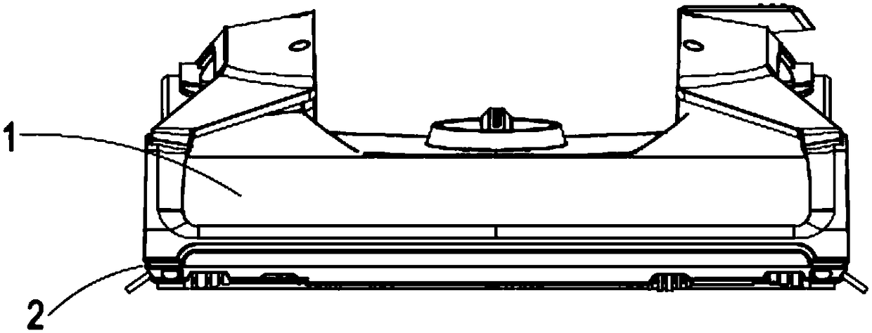
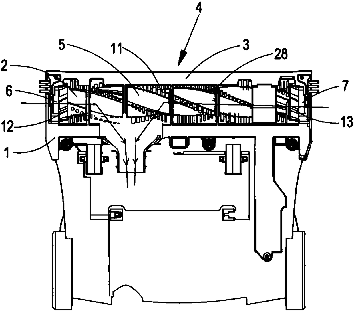
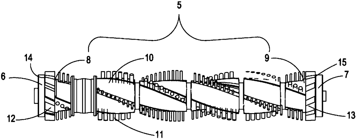
[0023] In this example, if Figure 1-Figure 5 The floor brush shown can be used on surface cleaning devices such as vacuum cleaners, steam cleaners, etc. It has a housing 1, the front part of the housing 1 is provided with a dust suction port 2 facing downwards, and the inner side of the housing 1 is adjacent to the dust suction port 2. A roller brush installation cavity 3 is installed in the roller brush installation cavity 3 The rolling brush assembly 4, the air flow is formed between the rolling brush installation chamber 3 and the dust suction port 2, the rolling brush assembly 4 includes a rolling brush body 5 capable of rotating around a transverse axis line, and the two sides of the rolling brush body 5 have first ends The cover 6 and the second end cover 7, the rolling brush body 5 has a first side end 8, a second side end 9 an...


PUM


Abstract

The invention relates to a floor brush for a surface cleaning device. The floor brush comprises a shell, a dust collection opening located at the bottom of the shell, a rolling-brush installing cavityadjacent to the dust collection opening, a rolling brush assembly installed in the rolling-brush installing cavity and an airflow channel communicated with the dust collection opening, wherein the rolling brush assembly comprises a rolling brush body and end covers located on the two sides of the rolling brush body, the rolling brush body comprises a first side end part, a second side end part and a peripheral wall face arranged between the first side end part and the second side end part, the end covers are fixedly supported on the shell, and a wind wheel is fixedly arranged on the first side end part and / or the second side end part of the rolling brush body; when the rolling brush body rotates, an airflow whirlwind is formed at the wind wheel in the direction from outside to inside. Thefloor brush can effectively clean away dust at the edge of the floor brush, and occurrence of the blocking phenomenon caused when hair enters the rolling brush assembly is effectively relieved.

Description

technical field [0001] The invention belongs to the technical field of household appliances, and in particular relates to a floor brush used for a surface cleaning device. Background technique [0002] Now the conventional floor brush mouth is basically located in the center of the floor brush assembly or close to one side, so the suction generated by the suction mouth will have less influence on the edges on both sides (or the other side edge), and the reduced suction cannot form an effective wind speed flow , the dust on the edge cannot be effectively cleaned. In addition, the usual rolling brush assembly includes a rolling brush body, bristles arranged on the rolling brush body, and a motor that drives the rolling brush body to rotate. Now the conventional rolling brush assembly , The end cover of the roller brush and the body of the roller brush are in a state of relative motion. In order to keep them from rubbing against each other, there is a certain gap between the tw...

Claims


Application Information

Patent Timeline
IPC IPC(8): A47L9/04A47L11/40
CPCA47L9/04A47L9/0477A47L11/4041
Inventor 卞庄
Owner SUZHOU CHENGHE CLEANING EQUIP
Why Eureka
Try Eureka