
New pressing type rebound buffer lock

A pressing and locking technology, applied in furniture parts, home utensils, drawers, etc., can solve the problems of collision, failure to meet requirements, drawer impact sound, etc.

Active Publication Date: 2018-08-17
GUANGDONG UNIHOPPER PRECISION TECH CORPERATION LIMMITED
View PDF6 Cites 6 Cited by
  • Summary
  • Abstract
  • Description
  • Claims
  • Application Information

AI Technical Summary

Problems solved by technology

[0002] Existing bounce-back drawers often use a drawer bouncer to realize the opening and closing of the drawer by touching the drawer. However, the quality of the existing drawer bouncers varies. After a period of use, it is easy to get stuck or cannot be closed by pressing. Affect the use of the drawer; there are various working methods for the drawer guide rails on the market. Some guide rails can buffer and self-close when the drawer is closed, but they need to be pulled out manually; some guide rails can realize the rebound function, and the drawer can be pressed automatically. Pops up, but no cushioning effect when the drawer is closed, prone to drawer slamming sound
[0003] The Chinese patent 2017202328541 applied by the applicant discloses a push-type lock in a cabinet lock device with a push-type rebound lock, which enables the drawer to be closed by adding a rebound lock on the basis of the buffer guide rail. While having a cushioning effect, the drawer can automatically pop up after being pressed; however, when the lock is pressed and popped up, there will be a collision sound due to the collision between the transmission block and the rebound push block on the drive push block. In the drawers with high quiet requirements, the requirements are often not met

Method used


Image

  • New pressing type rebound buffer lock
  • New pressing type rebound buffer lock
  • New pressing type rebound buffer lock

Examples


Embodiment Construction

[0021] The present invention will be further described below in conjunction with specific examples.

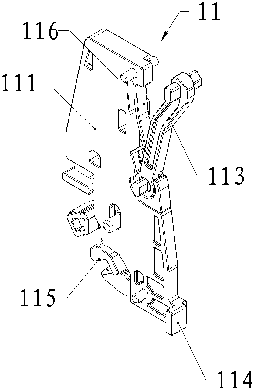
[0022] See attached figure 1 to attach Figure 7 As shown, in this embodiment, a new push-type rebound buffer lock includes a rebound lock 1. The rebound lock 1 of this embodiment is suitable for a drawer, that is, it also includes two symmetrically arranged on both sides of the drawer. The bump block 2 and the synchronous rod 3 on the side buffer guide rail; the housing 100 of the rebound lock 1 is slidably connected with the drawer bottom plate, and two groups of rebound locks 1 are arranged on the drawer bottom plate and the two ends of the synchronous rod 3 are respectively connected with the two Group rebound lock piece 1 cooperates.

[0023] In this embodiment, the rebound lock 1 includes a drive assembly 11 , a transmission assembly 12 and a linkage assembly 13 arranged in the housing 100 , and the result or locking function is realized through cooperation between the...


PUM


Abstract

The invention provides a new pressing type rebound buffer lock. The lock comprises a rebound lock which comprises a driving assembly arranged in a shell, a transmission assembly and a linkage assembly; the driving assembly comprises a driving mounting part, a driving push block which is installed on the driving mounting part in a reciprocating sliding mode and abuts against and cooperates with a bump on a buffer guide rail arranged in advance and a driving push rod hinged to the driving push block, the transmission assembly comprises a transmission mounting part, a transmission stop block hinged to the transmission mounting part, a telescopic spring with the two ends connected with the shell and the transmission mounting part respectively and a transmission rebound block which is formed onthe transmission mounting part and abuts against and cooperates with the driving rebound block, and the linkage assembly comprises a linkage rod and a linkage part performing reciprocating sliding ina linkage sliding groove formed in the shell in advance.

Description

technical field [0001] The invention relates to the technical field of cabinet lock devices, in particular to a novel push-type rebound buffer lock. Background technique [0002] Existing bounce-back drawers often use a drawer bouncer to realize the opening and closing of the drawer by touching the drawer. However, the quality of the existing drawer bouncers varies. After a period of use, it is easy to get stuck or cannot be closed by pressing. Affect the use of the drawer; there are various working methods for the drawer guide rails on the market. Some guide rails can buffer and self-close when the drawer is closed, but they need to be pulled out manually; some guide rails can realize the rebound function, and the drawer can be pressed automatically. It pops up, but there is no cushioning effect when the drawer is closed, and it is prone to drawer slamming sound. [0003] The Chinese patent 2017202328541 applied by the applicant discloses a push-type lock in a cabinet lock...

Claims


Application Information

Patent Timeline
IPC IPC(8): A47B88/463A47B88/467A47B88/90A47B88/477
CPCA47B88/463A47B88/467A47B88/477A47B88/90
Inventor 梁尔君吴嘉榆资斌祝灼芳
Owner GUANGDONG UNIHOPPER PRECISION TECH CORPERATION LIMMITED
Learn More