
Clothes drying machine steel wire rope installation method and steel wire rope installation device

A technology of installation device and installation method, which is applied to washing devices, hoisting devices, other drying devices, etc., can solve the problems of difficult assembly operation, long time-consuming, and easily messy lines, so as to save production site space and improve quality. Stability, the effect of simplifying the installation process

Pending Publication Date: 2018-08-14
GUANGDONG HOTATA TECH GRP
View PDF0 Cites 1 Cited by
  • Summary
  • Abstract
  • Description
  • Claims
  • Application Information

AI Technical Summary

Problems solved by technology

[0011] In the above steps, for the steps that need to store parts by category, it will increase the man-hours; the removed transmission shaft is also entrained with grease, and it needs to be cleaned and added with grease when reinstalling it, otherwise it is easy to cause secondary damage to the motor; the left and right wire ropes, left and right There are differences in the structure of the reels, which need to be stored and installed separately, which is time-consuming and prone to problems; when putting the reel with a wire rope, the assembly operation is difficult, and it is easy to mess up the wires and cause secondary operations. It is difficult to measure and adjust the length of wire ropes to be aligned
To sum up, the current wire rope installation method is complex and difficult, time-consuming and prone to problems

Method used


Image

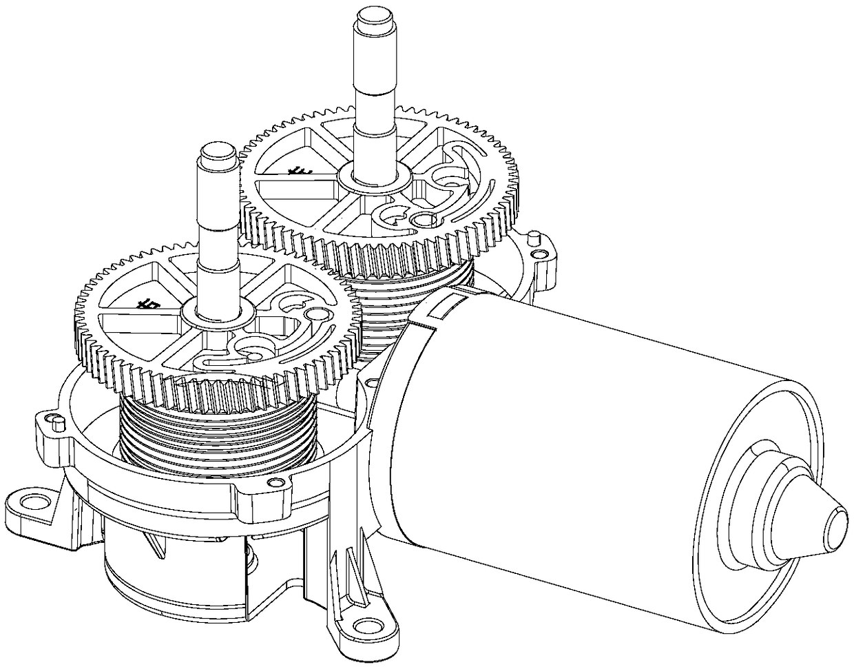
  • Clothes drying machine steel wire rope installation method and steel wire rope installation device
  • Clothes drying machine steel wire rope installation method and steel wire rope installation device
  • Clothes drying machine steel wire rope installation method and steel wire rope installation device

Examples


Embodiment Construction

[0042] The present invention will be further described in detail below in conjunction with the accompanying drawings and specific embodiments.

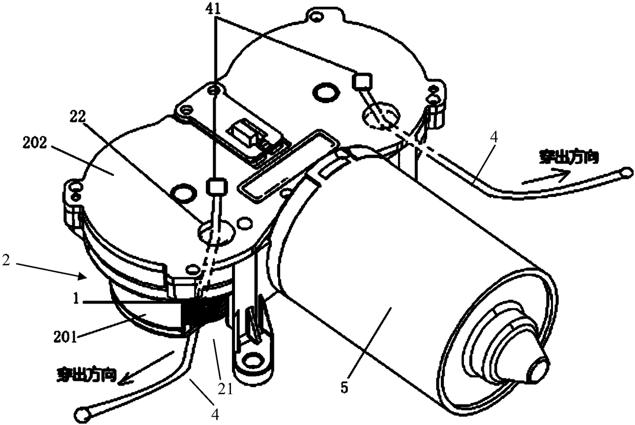
[0043] Such as Figure 10 As shown, a method for installing a wire rope of a clothes dryer in this embodiment includes:

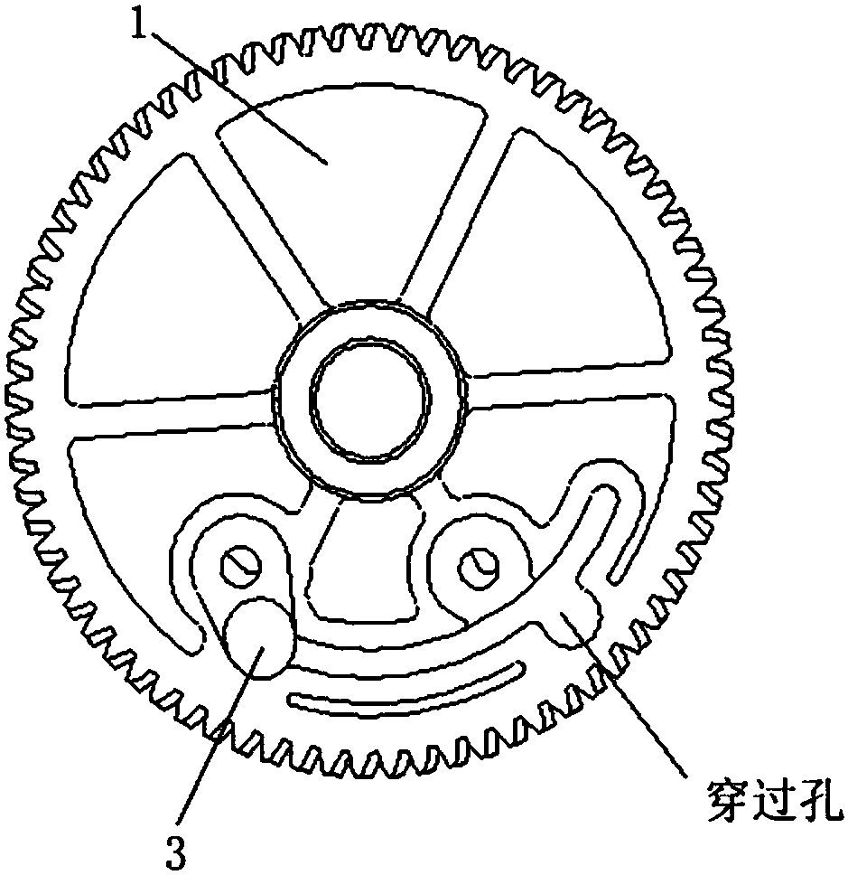
[0044] Pass the steel wire rope 4 through the wire passing structure of the motor assembly, and use the end 41 at the end of the steel wire rope 4 to buckle back into the fixing hole 3 (such as image 3 , 6 , 9 shown);

[0045] The motor 5 drives the reel to rotate, and the reel winds the wire rope 4;

[0046] Control the starting and stopping of the motor 5 corresponding to the reel, adjust the rotation amount of the two reels on the left and right, so that the extensions of the two steel ropes 4 on the left and right are equal.

[0047] Wherein, the motor assembly is an assembly including the motor 5 , the reel 1 , and the gearbox housing 201 . In this way, the left reel and the right reel can be respectivel...


PUM


Abstract

The invention discloses a clothes drying machine steel wire rope installation method. The method comprises the steps that steel wire ropes penetrates through a wire passing structure of a motor assembly and are inversely buckled to fixing holes through end sockets at the tail ends of the steel wire ropes, wire winding wheels are driven by motors to rotate, and the steel wire rope is wound by the wire winding wheels; the motors corresponding to the wire winding wheels are controlled to be started and stopped, the rotating amount of the left and right wire winding wheels is adjusted, and the stretching-out lengths of the left and right steel wire ropes are made equal. The invention further discloses a steel wire rope installation device using the clothes drying machine steel wire rope installation method. The device comprises the wire winding wheels, shells used for containing the wire wining wheels and the wire passing structure through which the steel wire ropes penetrate, the wire winding wheels are pivoted into the shells, the sides of the shells are provided with gaps which correspond to the wire winding wheels in position, the wire passing structure at least comprises the fixing holes formed in the wire winding wheels, and the fixing holes are used for inverted fastening of the tail ends of the steel wire ropes. The installation process of the steel wire ropes can be simplified.

Description

technical field [0001] The invention relates to an assembly technology of a clothes dryer, in particular to a method for installing a wire rope of a clothes dryer and a wire rope installation device. Background technique [0002] Clothes drying machine (or electric clothes drying machine, electric clothes drying rack) is an automatic lifting and lowering automatic device driven by an electric drive device, which drives a wire rope, a telescopic frame (or a folding piece assembly, a fork) type lifting mechanism) to drive the clothes-drying pole to realize the lifting of the clothes-drying pole. [0003] The electric drive device is generally a DC motor as the power source of the clothes dryer, and a wire rope is used as the traction medium. One end of the wire rope is fixed on the reel inside the motor, and the other end is fixed on the clothes rail, which is rotated by the motor and further drives the reel. The wire wheel rotates, thereby driving the wire rope to pull the c...

Claims


Application Information

Patent Timeline
Patent Type & Authority Applications(China)
IPC IPC(8): B66D1/60B66D1/26B66D1/12B66D1/30B66D1/34D06F57/12
CPCD06F57/12B66D1/12B66D1/26B66D1/30B66D1/34B66D1/60
Inventor 沈汉标陈南兵黄安川
Owner GUANGDONG HOTATA TECH GRP
Learn More