Mechanical cutting machine

A cutting machine and mechanical technology, which is applied in the direction of metal processing machinery parts, shearing devices, maintenance and safety accessories, etc., can solve the problems of poor protection, loud noise, and random dust discharge, so as to reduce noise pollution and enhance the safety factor of use , Noise effect isolation effect

Inactive Publication Date: 2018-08-10
安吉联政知识产权咨询有限公司
View PDF0 Cites 0 Cited by
  • Summary
  • Abstract
  • Description
  • Claims
  • Application Information

AI Technical Summary

Problems solved by technology

[0004] The purpose of the present invention is to provide a mechanical cutting machine to solve the problems of excessive noise, disorderly discharge of dust and poor protection in the prior art

Method used


Image

  • Mechanical cutting machine
  • Mechanical cutting machine

Examples


Embodiment Construction

[0014] The following will clearly and completely describe the technical solutions in the embodiments of the present invention with reference to the accompanying drawings in the embodiments of the present invention. Obviously, the described embodiments are only some, not all, embodiments of the present invention. Based on the embodiments of the present invention, all other embodiments obtained by persons of ordinary skill in the art without making creative efforts belong to the protection scope of the present invention.

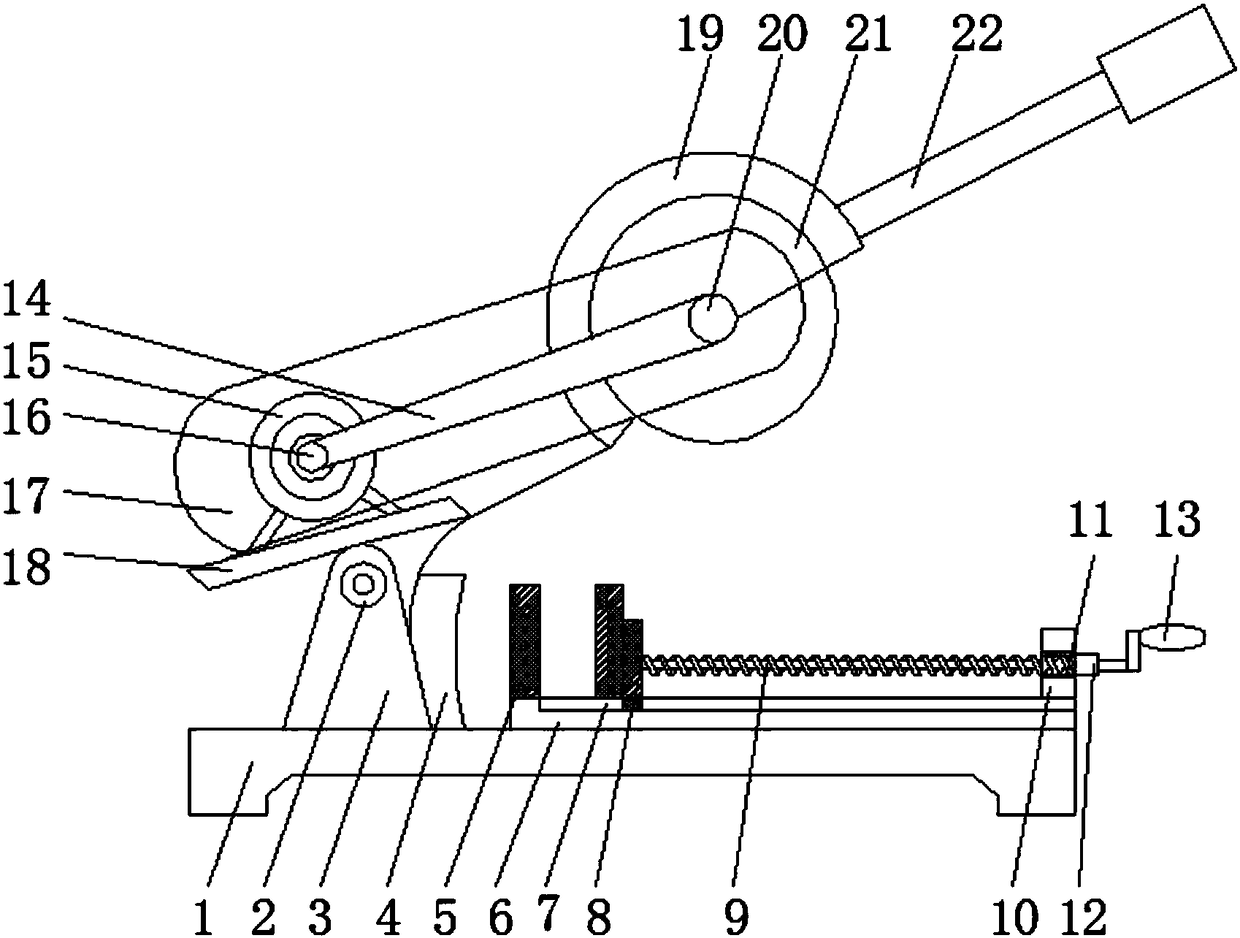
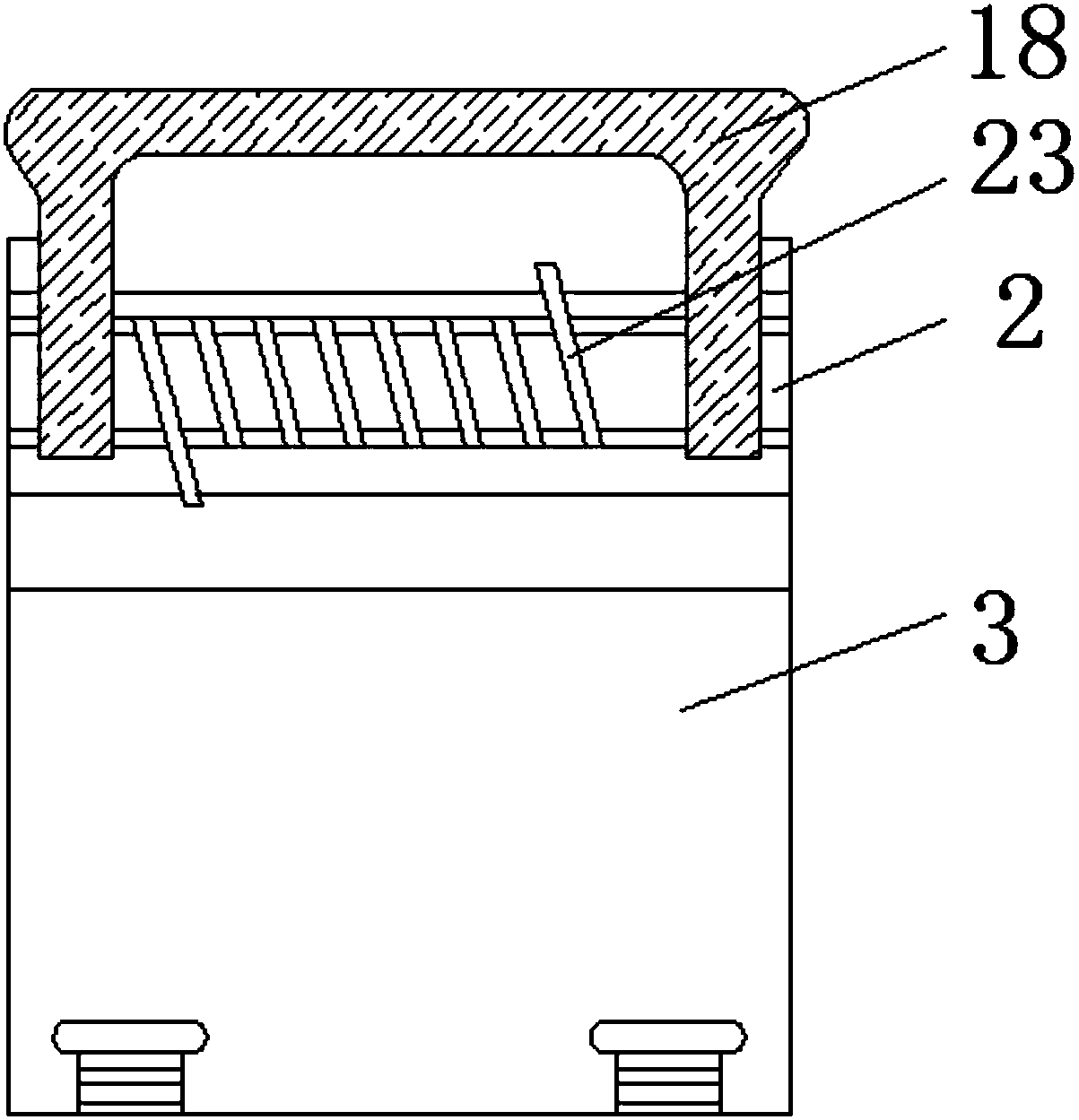
[0015] see Figure 1~2 , in an embodiment of the present invention, a mechanical cutting machine includes a bottom plate 1, the bottom plate 1 is used to support the body, a motor frame 3 is installed above the bottom plate 1, the motor frame 3 is used to fix the motor 15, and the motor frame 3 is located on the bottom plate On one side of 1, a linkage shaft 2 is installed in the motor frame 3, and the linkage shaft 2 is used to drive the turnover plate 18 to ...


PUM


Abstract

The invention discloses a mechanical cutting machine comprising a bottom plate. A motor frame is mounted on the upper portion of the bottom plate and located on one side on the bottom plate; a linkageshaft is mounted in the motor frame, and a positioning spring is mounted on the linkage shaft; a turning plate is mounted on the upper portion of the linkage shaft, and a motor is mounted on the upper portion of the turning plate; a first belt disc is mounted in the motor; a first protective plate is mounted on the outer side of the motor; a belt is mounted on one side of the first belt disc; anda second belt disc is mounted at one end of the belt, and a cutting piece is mounted on the outer side of the second belt disc. A dustproof belt is arranged on the mechanical cutting machine and located on the rear portion of the cutting piece, in the using process, in the cutting direction, air is blown in the rotating direction of the cutting piece, thus dust and residual iron filings are blowninto the dustproof belt, and the problem of breathing difficulty of a user is solved.

Description

technical field [0001] The invention relates to the field of cutting machines, in particular to a mechanical cutting machine. Background technique [0002] With the development of the modern mechanical processing industry, the requirements for cutting quality and precision are constantly improving, and the requirements for improving production efficiency, reducing production costs, and highly intelligent automatic cutting functions are also increasing. Some small and medium-sized enterprises in our country even use manual cutting and semi-automatic cutting methods in some large enterprises. The amount of steel used in my country's machinery industry has reached more than 300 million tons, and the amount of steel cut is very large; with the development of modern machinery industry , The requirements for work efficiency and product quality of plate cutting processing are also improved at the same time. Therefore, the market potential of CNC cutting machines is still very large...

Claims


Application Information

Patent Timeline
Patent Type & Authority Applications(China)
IPC IPC(8): B23D19/00B23Q11/00
CPCB23D19/00B23Q11/005
Inventor 俞海强
Owner 安吉联政知识产权咨询有限公司
Why Eureka
Try Eureka