
Low-temperature-drift high-accuracy current source suitable for any resistor type

A current source, low temperature drift technology, applied in the direction of adjusting electrical variables, control/regulating systems, instruments, etc., can solve the problems of not easy to obtain, the current source is not easy to realize, etc., to achieve the effect of current source and voltage source

Inactive Publication Date: 2018-08-07
深圳市依珂新微电子有限公司
View PDF7 Cites 2 Cited by
  • Summary
  • Abstract
  • Description
  • Claims
  • Application Information

AI Technical Summary

Problems solved by technology

[0006] The two current source generation methods described require that the temperature coefficient of the resistance must be related to the temperature coefficient of a specific voltage source. In the semiconductor process, it is not easy to obtain a resistance with a specific temperature coefficient.
Therefore, this kind of current source with low temperature drift is often not easy to realize, based on this situation

Method used


Image

  • Low-temperature-drift high-accuracy current source suitable for any resistor type
  • Low-temperature-drift high-accuracy current source suitable for any resistor type

Examples


Embodiment 1

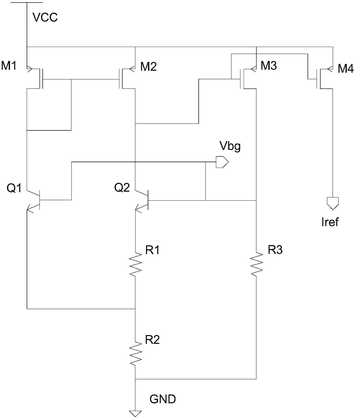
[0028] Such as figure 1 Shown, the circuit composition of the present invention:

[0029] Including a bandgap reference circuit composed of MOS transistors M1, M2, M3, PNP transistors Q1, Q2 and resistors R1, R2, R3, which generate a bandgap reference voltage Vdg;

[0030] The current source generation circuit includes a MOS transistor M4, which generates a low-temperature drift current source Iref.

[0031] Specifically, the sources of the MOS transistors M1, M2, and M3 are connected to the power supply VCC; the gate of the MOS transistor M2 is connected to the gate and drain of the MOS transistor M1, and the gate of the MOS transistor M3 is connected to the drain of the MOS transistor M2; The drain of M1 is connected to the collector of PNP transistor Q1, and the base of PNP transistor Q1 is connected to the base of PNP transistor Q2 to generate a bandgap reference voltage Vdg; the emitter of PNP transistor Q1 is grounded through resistor R2; the drain of MOS transistor M2 ...

Embodiment 2

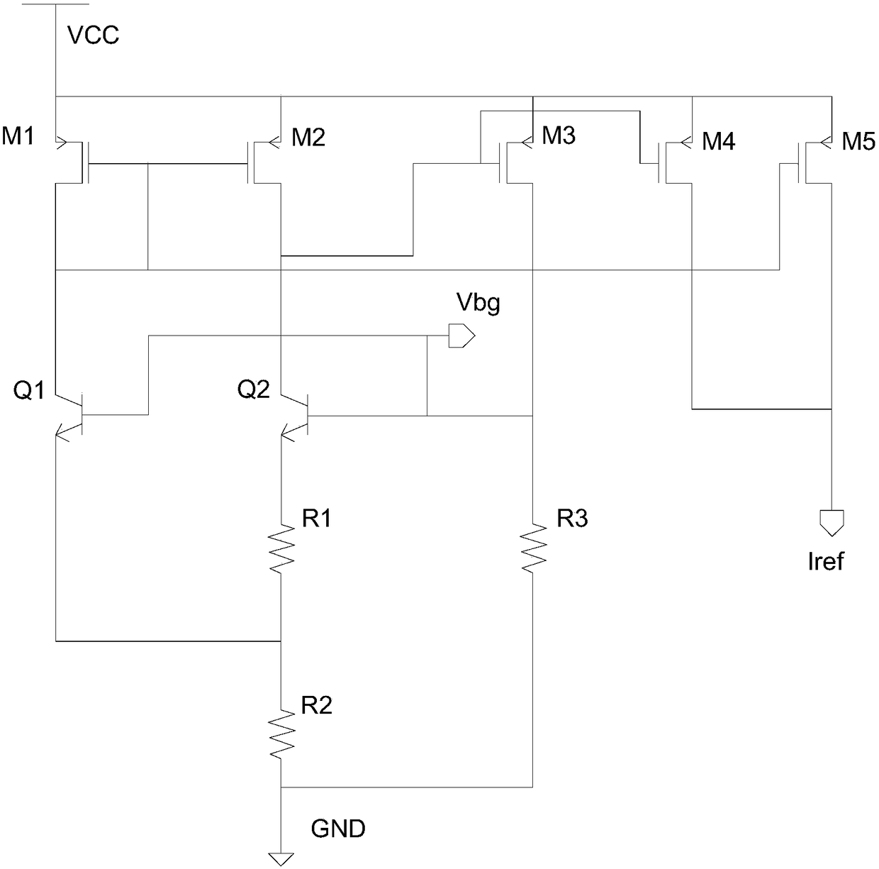
[0055] Such as figure 2 As shown, this embodiment is improved on the basis of the first embodiment, so that a current source with low temperature drift and a bandgap reference voltage with low temperature drift can be obtained at the same time.

[0056] The current source generation circuit also includes a MOS transistor M5; the source of the MOS transistor M5 is connected to the power supply VCC, the gate of the MOS transistor M5 is connected to the drain of the MOS transistor M1, and the drains of the MOS transistors M5 and M4 jointly generate a low-temperature drift current source Iref .

[0057] In order to obtain a low-temperature drift voltage source, ensure that Vbg is a bandgap reference voltage, that is, the temperature drift of Vbg is zero. The source-leakage current IM4 of the MOS transistor M4 mirrors the source-leakage current IM3 of the MOS transistor M3.

[0058] According to formula 5:

[0059] IM4=K1*IM3=K1*(Vbg / R3);

[0060] K1: ratio of width to length ...


PUM


Abstract

The invention discloses a low-temperature-drift high-accuracy current source suitable for any resistor type. The current source comprises a band-gap reference circuit and a current source generation circuit, the band-gap reference circuit generates band-gap reference voltage and is composed of MOS transistors M1, M2 and M3, PNP transistors Q1 and Q2 and resistors R1, R2 and R3, the current sourcegeneration circuit generates a low-temperature-drift current source and comprises a MOS transistor M4, a source electrode of the MOS transistor M4 is connected with a power source VCC while a grid electrode of the same is connected with that of the MOS transistor M3, and a drain electrode of the MOS transistor M4 generates a low-temperature-drift current source Iref. According to the principle ofband-gap reference, thermal voltage VT and PN node voltage VBE can be combined freely to obtain temperature coefficient similar to a process intrinsic resistor so as to quite conveniently obtain the low-temperature-drift current source which is completely independent from resistors with any specific temperature coefficient, and the current source and a voltage source with low temperature drift arerealized.

Description

technical field [0001] The invention belongs to the field of integrated circuit design, in particular to a low-temperature drift high-precision current source suitable for any resistance type. Background technique [0002] High-precision low-temperature drift current source or voltage source is widely used in integrated circuits, such as the bias of thermistor, which makes the system temperature detection simple and reliable. [0003] The current source is obtained by dividing the resistance by the voltage, that is, I=V / R. Among conventional high-precision current sources, to obtain a high-precision current source with low temperature drift, there are mainly the following methods: [0004] 1. The voltage is realized by the bandgap reference, and the resistance with low temperature drift is selected (the resistance can be realized by different types of combinations of positive and negative temperature coefficients), and the current source with low temperature drift is obtain...

Claims


Application Information

Patent Timeline
Patent Type & Authority Applications(China)
IPC IPC(8): G05F1/565
CPCG05F1/565
Inventor 唐顺柏
Owner 深圳市依珂新微电子有限公司
Learn More