
Occlusal state identifying method, occlusal state identifying apparatus

A state recognition and equipment technology, applied in image data processing, dental prosthesis, medical simulation, etc., can solve difficult problems

Inactive Publication Date: 2018-08-03
FUJITSU LTD
View PDF9 Cites 6 Cited by
  • Summary
  • Abstract
  • Description
  • Claims
  • Application Information

AI Technical Summary

Problems solved by technology

Therefore, it is not easy to adjust the positional relationship between the maxilla image and the mandible image, each having a direction and inclination according to the scanning state, to be able to generate an occlusal image

Method used


Image

  • Occlusal state identifying method, occlusal state identifying apparatus
  • Occlusal state identifying method, occlusal state identifying apparatus
  • Occlusal state identifying method, occlusal state identifying apparatus

Examples


Embodiment Construction

[0030] Hereinafter, an occlusion state recognition method, an occlusion state recognition device, and a storage medium will be described with reference to the accompanying drawings. It is intended that the technical scope of the present application is not limited to the embodiments of the present application, and equivalents of the scope of the claims are included in the scope of the present application.

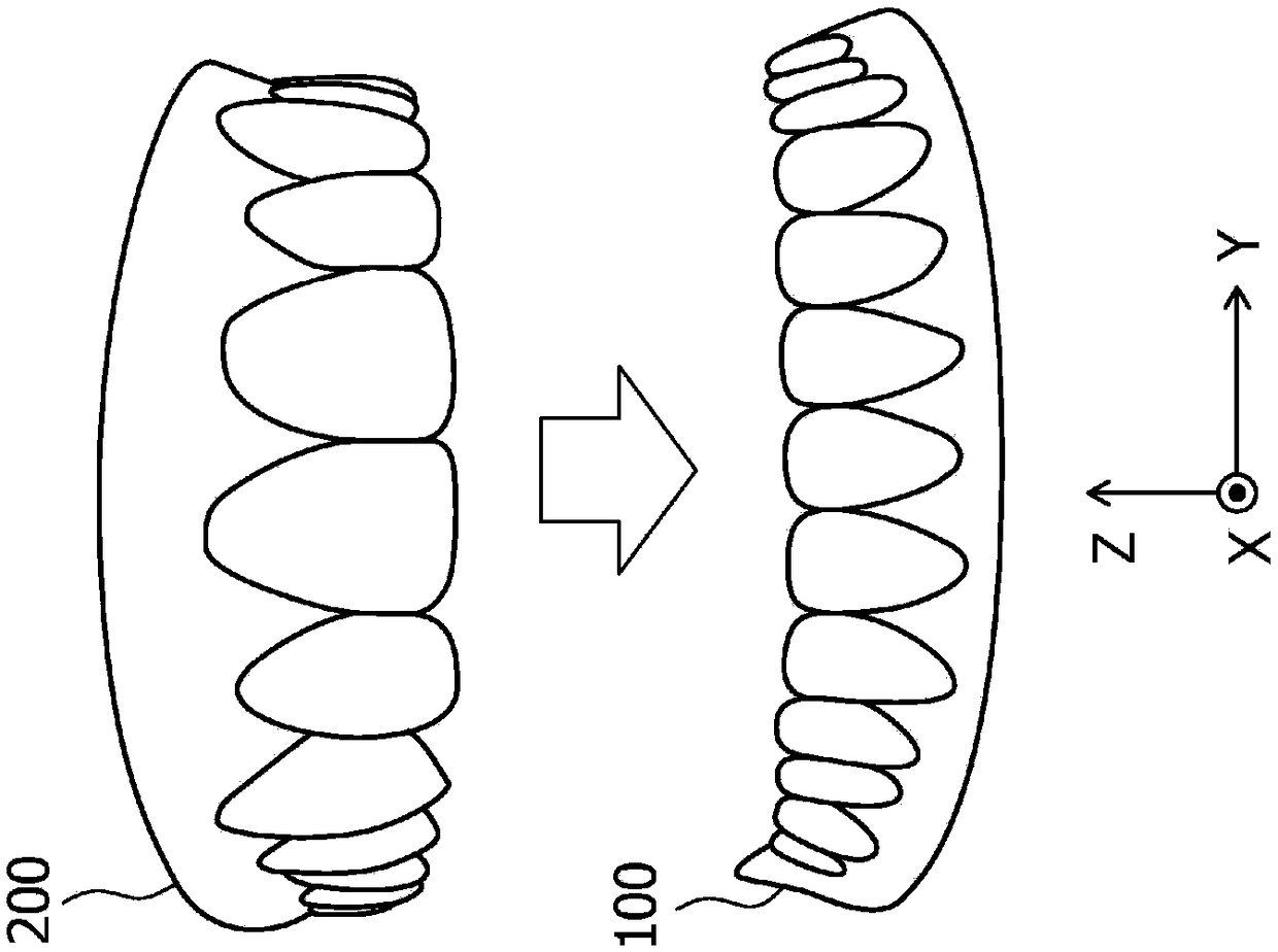
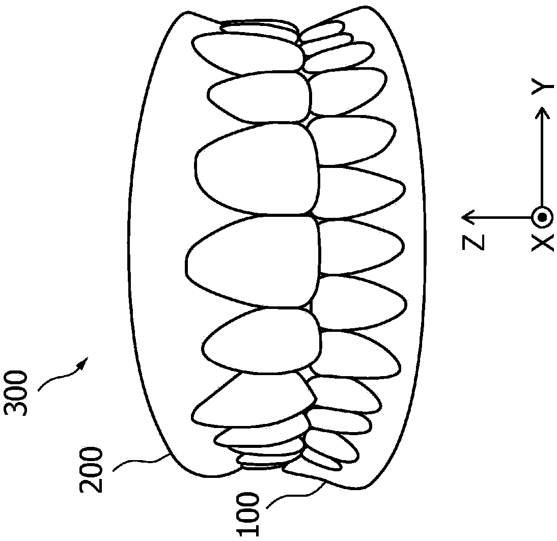
[0031] Figure 1A is a diagram showing an example of images arranged oppositely, in which a maxilla image and a mandible image are arranged such that corresponding teeth face each other. Figure 1B is a diagram showing an example of an occlusal image in which a dynamic simulation is performed to make Figure 1A The image of the upper jaw shown is shifted so that the upper and lower teeth mesh.

[0032] In the occlusal state recognition computer program, the jaw shape data acquiring unit acquires mandible shape data representing the mandible image 100 and maxilla shape data r...


PUM


Abstract

Provided is an occlusal state identifying method executed by a processor included in an occlusal state identifying apparatus. The occlusal state identifying method includes obtaining maxillary shape data and mandibular shape data; arranging a maxillary image including a plurality of maxillary teeth corresponding to the obtained maxillary shape data and a mandibular image including a plurality of mandibular teeth corresponding to the obtained mandibular shape data such that corresponding teeth oppose each other; executing a moving process of moving at least one of the arranged maxillary image and mandibular image by executing a dynamic simulation; and identifying a positional relationship between the maxillary image and the mandibular image after the moving process as a positional relationship corresponding to an occlusal state of the maxillary teeth included in the maxillary image and the mandibular teeth included in the mandibular image.

Description

technical field [0001] The embodiments discussed herein relate to an occlusion state recognition method, an occlusion state recognition device, and a storage medium. Background technique [0002] It is known to use tooth shape data representing a tooth shape including a crown shape in dental computer-aided design (CAD) and computer-aided manufacturing (CAM) software having various functions. For example, it is known that arrangement information representing at least the positional relationship between the subject's first and second molars is acquired from an acquired image of the subject's oral cavity, and that the subject's other position is predicted from the acquired arrangement information. Eruption dates of second molars (see, for example, Japanese Laid-Open Patent Publication No. 2012-45247). It is also known to detect the position and orientation of an object for identification and to obtain the spatial relationship between the maxilla and mandible of a dental patien...

Claims


Application Information

Patent Timeline
Patent Type & Authority Applications(China)
IPC IPC(8): G06T7/73G06T3/00A61C19/05
CPCG06T7/73A61C19/05G06T2207/30036G06T3/147G06T7/30A61B5/0088A61C9/0053G16H50/50A61C2007/004G06T19/20
Inventor 大竹亮介梅川克己石村达清
Owner FUJITSU LTD
Learn More