Drive device for displacing a vehicle part, comprising a magnetic braking unit

A technology for vehicle parts and driving equipment, which is applied to switches with brake parts, vehicle parts, wing fan parts, etc. question

Active Publication Date: 2018-07-31
BROSE FAHRZEUGTEILE GMBH & CO KG
View PDF10 Cites 0 Cited by
  • Summary
  • Abstract
  • Description
  • Claims
  • Application Information

AI Technical Summary

Problems solved by technology

[0008] Such conventional braking devices are complex and have a considerable installation space requirement

Method used


Image

  • Drive device for displacing a vehicle part, comprising a magnetic braking unit
  • Drive device for displacing a vehicle part, comprising a magnetic braking unit
  • Drive device for displacing a vehicle part, comprising a magnetic braking unit

Examples


Embodiment Construction

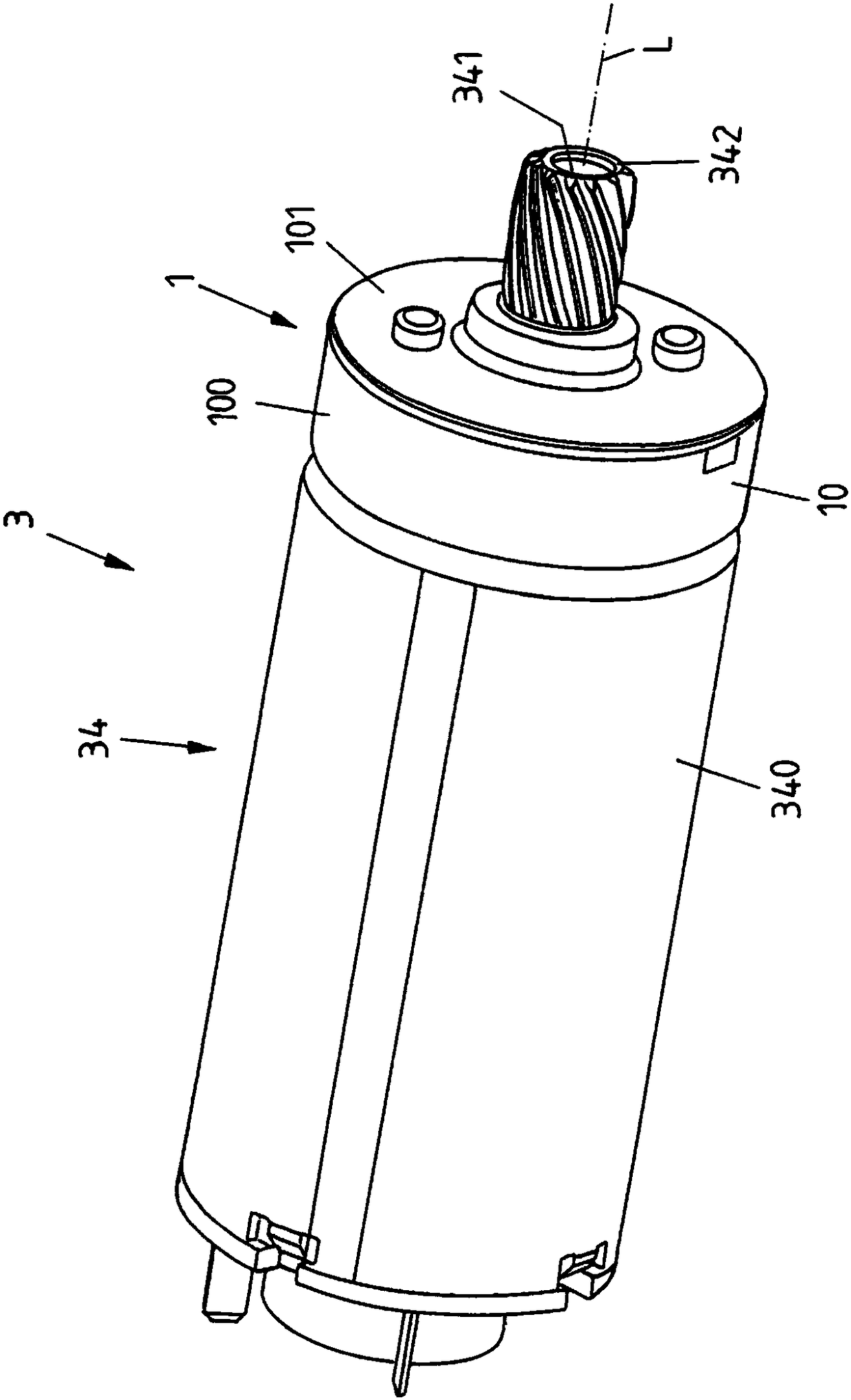
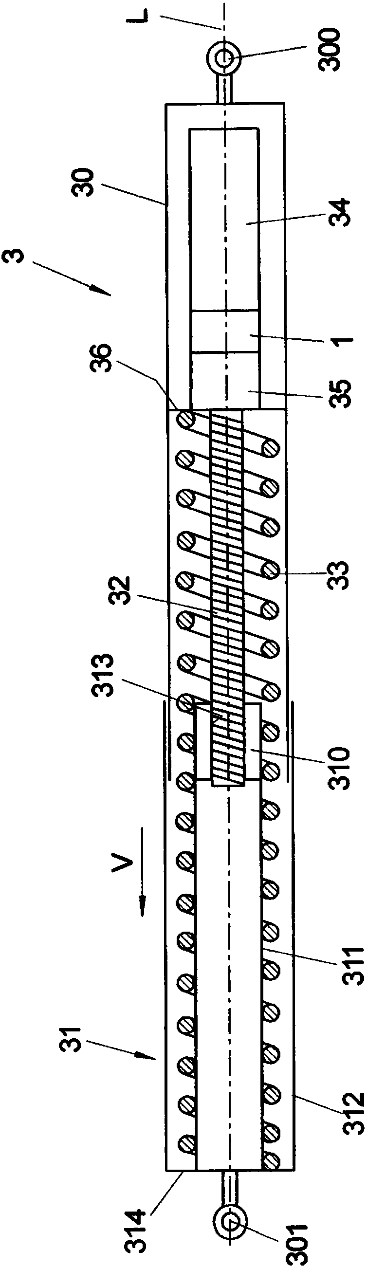
[0052] figure 1 The drive device 3 is shown in perspective, which has an electric drive 34 and a permanent magnet brake 1 . Electric drive 34 is designed as an electric motor and has, in housing 340 , a stator that is fixed relative to housing 340 and a rotor that is rotatable relative to the stator. The rotor is rotatable about a longitudinal axis L and drives a driven shaft 341 on which is arranged a transmission 35 arranged downstream (cf. Figure 3A and 3B ) of the pinion element 342 to adjust the vehicle components.

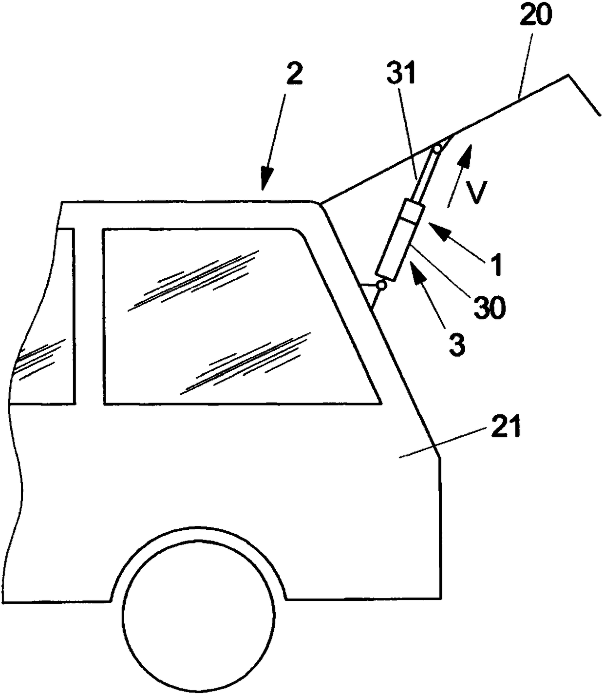
[0053] as from figure 2 As can be seen in FIG. 2 , a drive device 3 of this type is used, for example, to adjust a rear lid 20 of a vehicle 2 . Drive unit 3 acts in a known manner between rear lid 20 and body 21 of vehicle 2 .

[0054] In principle, however, a drive device 3 of the type described here can also be used to adjust completely different types of vehicle components.

[0055] The drive device 3 can be designed, for example, as a screw drive,...


PUM


Abstract

A drive device (3) for displacing a vehicle part, in particular a tailgate (20), comprises an electric drive (34) for driving the vehicle part, the electric drive comprising a drive shaft (341) for transferring a displacement force to the vehicle part, and a first braking device (1), operatively connected to the drive shaft (341), which has a permanent magnet element (12, 14) and is designed to provide a braking force for arresting the vehicle part in a position currently adopted. In addition, a second braking device (4) is provided which is designed to switch the electric drive (34) into a generative brake operation in order to feed power generated by the drive at least partially back into the drive and thus to provide a braking force for braking a movement of the vehicle part. In this way, a drive device with a permanent magnet brake is provided which can be designed simply and in a space saving way to provide a reliable braking force.

Description

technical field [0001] The invention relates to a drive unit for adjusting vehicle components and a method for operating a drive unit according to the preamble of claim 1 . Background technique [0002] Such a drive device includes an electric drive for driving a vehicle component. The electric drive has an output shaft for transmitting the adjusting force to the vehicle component. A first braking device is connected to the output shaft, which has at least one permanent magnet element and is designed to provide a braking force for securing the vehicle component in the currently assumed position. [0003] In the drive device known from EP 1 940 012 A1, the braking device in the form of a so-called hysteresis brake has a plate-shaped carrier element connected to the driven shaft in a rotationally fixed manner, for example an annular ring made of soft magnetic material The hysteresis element is fixed on the carrier element. Two permanent magnets on the stator are opposite th...

Claims


Application Information

Patent Timeline
IPC IPC(8): E05F15/622
CPCE05Y2201/258E05Y2900/546E05F15/622E05F15/614B60J5/10B62D33/027E05F3/00E05Y2201/438E05Y2201/442E05Y2201/686E05Y2201/70E05Y2201/702E05Y2201/716H02P31/00
Inventor 弗洛里安·韦尔克
Owner BROSE FAHRZEUGTEILE GMBH & CO KG
Why Eureka
Try Eureka