A projection display system
A technology of projection display and light modulator, which is applied in the field of projection display, can solve the problems of low contrast ratio of projection display system, achieve the effect of improving image quality, improving light utilization rate, and solving high cost and low effect
- Summary
- Abstract
- Description
- Claims
- Application Information
AI Technical Summary
Problems solved by technology
Method used
Image

Examples
Embodiment 1
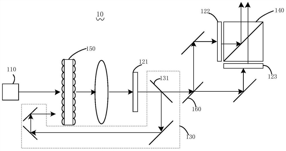
[0037] See figure 1 ,like figure 1 Shown is a schematic structural diagram of a projection display system according to Embodiment 1 of the present invention. The projection display system 10 includes a light emitting device 110, a first light modulation system, a second light modulation system, and a light recycling system 130, wherein the first light modulation system includes a first The light modulator 121 , the second light modulation system includes a second light modulator 122 and a third light modulator 123 .
[0038] In this embodiment, the light emitting device 110 emits the first light. The first light modulator 121 of the first light modulation system is located on the optical path of the first light, and is used for modulating the first light, and emitting the first image light and the first non-image light. Subsequently, the first image light is incident on the second light modulation system, and the second light modulation system is located on the optical pat...
Embodiment 2
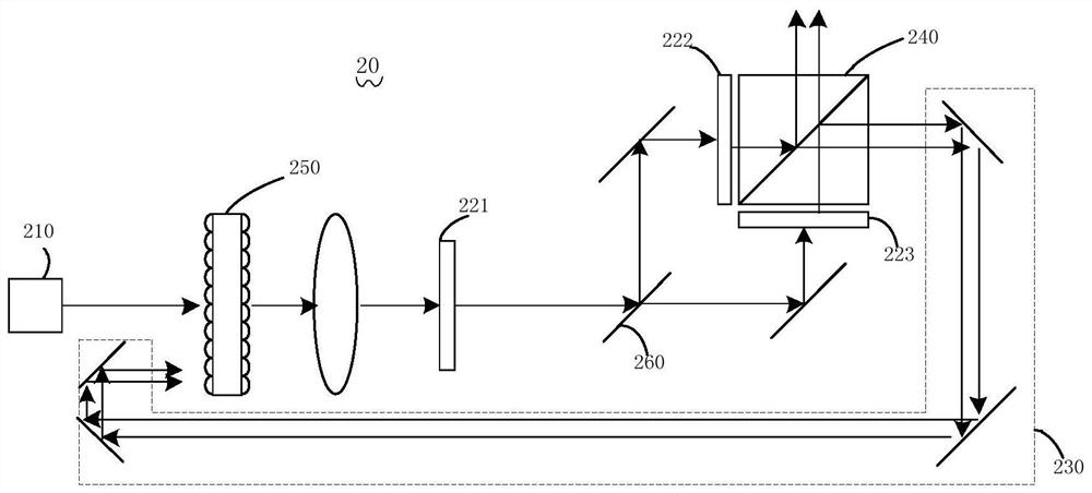
[0070] See figure 2 ,like figure 2 Shown is a schematic structural diagram of a projection display system according to Embodiment 2 of the present invention. The projection display system 20 includes a light emitting device 210, a first light modulation system, a second light modulation system, and a light recycling system 230, wherein the first light modulation system includes a first The light modulator 221, the second light modulation system includes a second light modulator 222 and a third light modulator 223 connected in parallel in the light path.
[0071] In this embodiment, the light emitting device 110 emits the first light. The first light modulator 221 of the first light modulation system is located on the optical path of the first light, and is used for modulating the first light, and emitting the first image light and the first non-image light. Subsequently, the first image light is incident on the second light modulation system, and the second light modulatio...
Embodiment 3
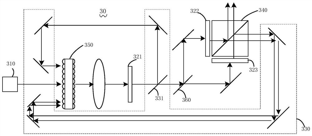
[0079] See image 3 ,like image 3 Shown is a schematic structural diagram of a projection display system according to Embodiment 3 of the present invention. The projection display system 30 includes a light emitting device 310, a first light modulation system, a second light modulation system, and a light recycling system 330, wherein the first light modulation system includes a first The light modulator 321 , the second light modulation system includes a second light modulator 322 and a third light modulator 323 connected in parallel in the light path, and the projection display system 30 also includes a light splitting element 360 , a light combination device 340 and a light uniform device 350 .
[0080] In this embodiment, the light emitting device 310 emits the first light. The first light modulator 321 of the first light modulation system is located on the optical path of the first light, and is used for modulating the first light, and emitting the first image light and...
PUM
 Abstract
Description
Claims
Application Information
 - R&D
- Intellectual Property
- Life Sciences
- Materials
- Tech Scout
- Unparalleled Data Quality
- Higher Quality Content
- 60% Fewer Hallucinations
Browse by: Latest US Patents, China's latest patents, Technical Efficacy Thesaurus, Application Domain, Technology Topic, Popular Technical Reports.
© 2025 PatSnap. All rights reserved.Legal|Privacy policy|Modern Slavery Act Transparency Statement|Sitemap|About US| Contact US: help@patsnap.com