Eureka AIR delivers breakthrough ideas for toughest innovation challenges, trusted by R&D personnel around the world.

Ring-block friction wear testing machine

A technology of friction and wear test and friction pair, which is applied in the direction of testing wear resistance, measuring devices, instruments, etc., can solve the problems of inaccurate simulation, single friction form, and inability to realize accurate measurement of friction force, so as to ensure basic stability and improve The effect of cooling efficiency

Active Publication Date: 2018-07-31
HENAN UNIV OF SCI & TECH
View PDF4 Cites 3 Cited by
  • Summary
  • Abstract
  • Description
  • Claims
  • Application Information

AI Technical Summary

Problems solved by technology

[0003] At present, the main structure of the ring-block friction and wear testing machine is mostly the same, and most of them cannot achieve accurate quantitative loading of radial force and accurate detection of friction force, and the friction form that can be provided is single
For example, the patent publication number is CN105158100A "Abrasion Gap Adjustment Type Ring Block Friction and Wear Tester", the radial force loading method adopted is purely manual loading, and there is no accurate detection equipment suitable for the loaded radial force , it is impossible to complete the precise quantitative loading of the radial force of the test piece; the lubrication method adopted by the friction pair is fixed, which cannot accurately simulate the lubrication conditions of the friction pair under various actual working conditions. The friction detection method is relatively simple and cannot Accurate measurement of friction

Method used


Image

  • Ring-block friction wear testing machine
  • Ring-block friction wear testing machine
  • Ring-block friction wear testing machine

Examples


Embodiment Construction

[0027] The technical solution of the present invention will be further described through specific implementation manners below in conjunction with the accompanying drawings.

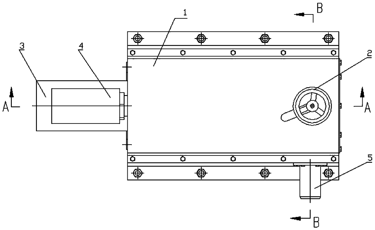
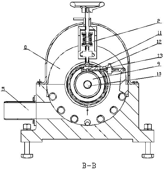
[0028] As shown in the figure, a ring-block friction and wear testing machine includes a body 1 of the testing machine, a power drive device, a main shaft 7, a ring-block friction pair, a force measuring device 12 and a radial loading device 2, and the ring-block friction The pair is located at the end of the main shaft 7 and consists of a test ring 13 and a test block 11. The hollow part at the end of the main shaft 7 is provided with a tapered threaded hole, and the tapered shaft 9 used to install the test ring 13 is installed in the tapered threaded hole at the end of the main shaft 7. , and locked by the locking screw 10, the test ring 13 is installed on the cone shaft 9, and the test ring 13 is fixed on the cone shaft 9 by the lock nut matched with the end of the cone shaft 9; the force measurement ...


PUM


Abstract

A ring-block friction wear testing machine comprises a machine body, a power driving device, a main shaft, a ring-block friction pair and a radial loading device, wherein a test ring in the ring-blockfriction pair is mounted on the main shaft; the power driving device drives the main shaft to drive the test ring to rotate; a force measuring device is arranged between the radial loading device andthe ring-block friction pair; the force measuring device mainly comprises a sample holder, a tension sensor, a hinge rod and a pull rod holder which are sequentially connected; the hinge rod is rotationally connected with the pull rod holder; the pull rod holder is fixed to the machine body; a test sample is mounted at the lower part of the sample holder; the test sample contacts with the test ring to form the ring-block friction pair; a medium channel for providing different lubricating media for the ring-block friction pair is formed in the sample holder; a loading end of the radial loadingdevice acts on the sample holder to perform radial loading and quantitative adjustment on the ring-block friction pair. The ring-block friction wear testing machine can accurately measure friction ofthe ring-block friction pair in real time, and can accurately simulate friction pair lubricating conditions under various actual working conditions.

Description

technical field [0001] The invention belongs to the field of testing machine design and application, in particular to a testing machine for ring-block friction and wear tests. Background technique [0002] The testing machine is a special machine that verifies the quality or performance of products or materials according to the design requirements. There are different types of testing machines depending on the test objects and test items. Ring-block friction and wear testing machine is a commonly used testing machine. [0003] At present, the main structures of ring-block friction and wear testing machines are mostly the same, and most of them cannot achieve accurate quantitative loading of radial force and accurate detection of friction force, and can provide a single form of friction. For example, the patent publication number is CN105158100A "Abrasion Gap Adjustment Type Ring Block Friction and Wear Tester", the radial force loading method adopted is purely manual loadi...

Claims


Application Information

Patent Timeline
Patent Type & Authority Applications(China)
IPC IPC(8): G01N3/56G01N3/06G01N3/02
CPCG01N3/02G01N3/06G01N3/56G01N2203/0676
Inventor 董永祥司东宏李杨薛玉君李济顺李航
Owner HENAN UNIV OF SCI & TECH
Why Eureka
Eureka Blog
Learn More