Two-stage ejection one-machine-and-two-temperature refrigeration system for expansion work recovery

A two-stage injection and refrigeration system technology, which is applied in the direction of refrigerators, refrigeration components, refrigeration and liquefaction, etc., can solve the problems of refrigeration system performance degradation, low pressure of low-temperature evaporator, high pressure ratio of compressor, etc., to save resources , Reduce the inlet enthalpy and increase the effect of suction pressure

Inactive Publication Date: 2018-07-31
TIANJIN UNIV OF COMMERCE
View PDF8 Cites 5 Cited by
  • Summary
  • Abstract
  • Description
  • Claims
  • Application Information

AI Technical Summary

Problems solved by technology

[0002] In the field of cold chain logistics refrigeration and refrigeration, the refrigeration device stores different items and requires different cold room temperatures. Two cold rooms with different evaporation temperatures can use a refrigeration system with one machine and two warehouses. Usually, a thermal expansion valve is used to adjust different evaporation temperatures. For the liquid supply of the evaporator, in order to ensure the unobstructed return air of each evaporator and prevent the high-pressure evaporator from passing gas to the low-pressure evaporator, it is necessary to install an evaporating pressure regulating valve at the outlet of the evaporator with a relatively low evaporation temperature. The outlet of the evaporator is equipped with a one-way valve, the system is relatively complex, the pressure of the low-temperature evaporator is low, the pressure ratio of the compressor is large, and the power consumption is large.

Method used


Image

  • Two-stage ejection one-machine-and-two-temperature refrigeration system for expansion work recovery

Examples


Embodiment Construction

[0011] The present invention will be described in further detail below in conjunction with the accompanying drawings and specific embodiments.

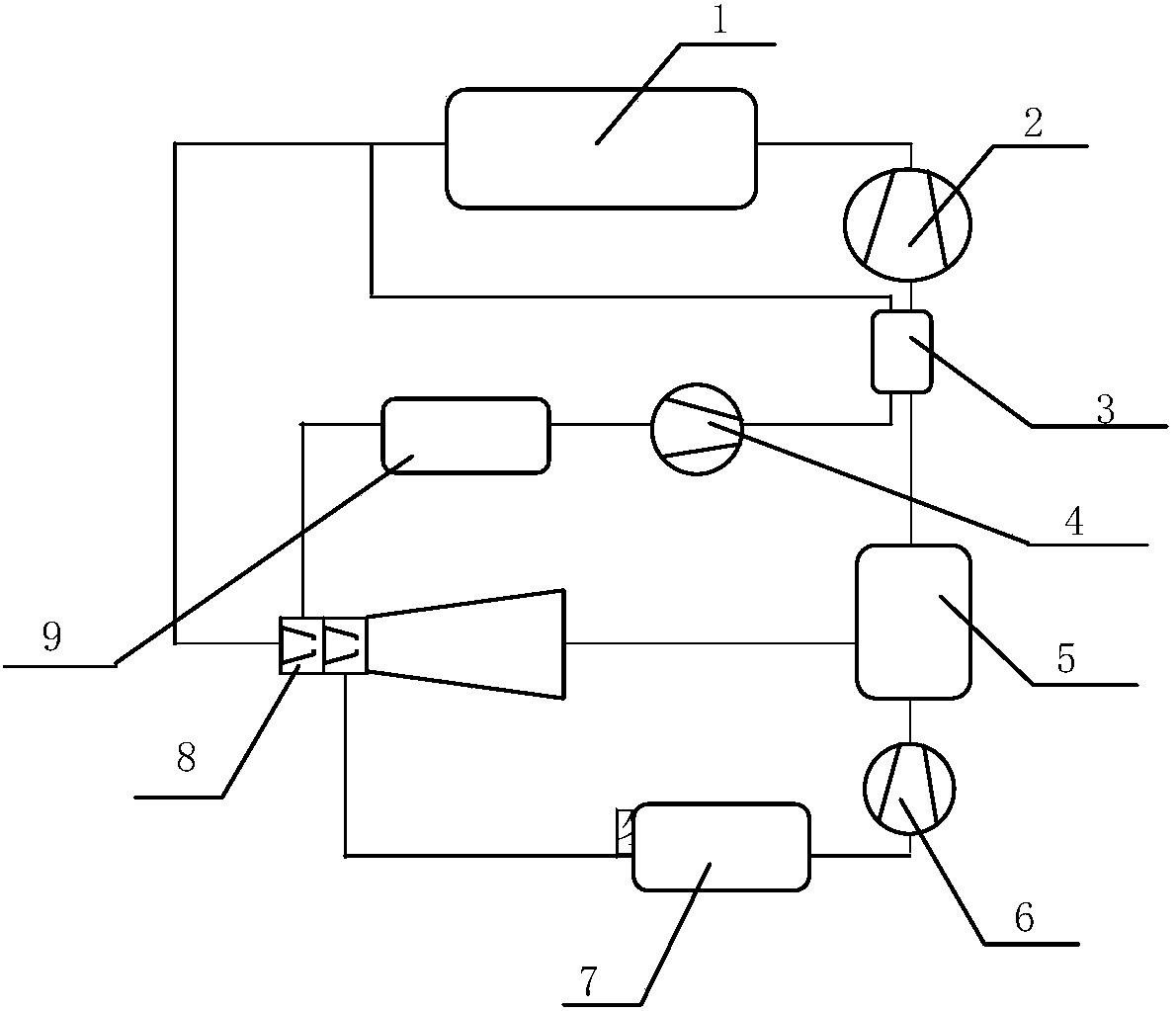
[0012] see figure 1 As shown, a two-stage ejector one-machine dual-temperature refrigeration system that recovers expansion work includes:

[0013] Condenser 1, refrigeration compressor 2, regenerator 3, first expander 4, gas-liquid separator 5, second expander 6, second evaporator 7, secondary jet ejector 8, first evaporator 9;;

[0014] The outlet of the refrigeration compressor 2 is connected to the inlet of the condenser 1, and the outlet of the condenser 1 is divided into two paths, one path is connected with the main fluid inlet of the secondary jet ejector 8, and the other path is connected with the high-pressure fluid of the regenerator 3 The inlet is connected, the high-pressure fluid outlet of the regenerator 3 is connected with the inlet of the first expander 4, the outlet of the first expander 4 is connected with the inl...


PUM


Abstract

The invention discloses a two-stage ejection one-machine-and-two-temperature refrigeration system for expansion work recovery. According to the Two-stage ejection one-machine-and-two-temperature refrigeration system for expansion work recovery, a refrigeration compressor outlet and a condenser inlet are connected, one path of a condenser outlet is connected with a two-stage jetting and ejection device main fluid inlet, and the other path of the condenser outlet is connected with a heat regenerator high-pressure fluid inlet. A heat regenerator high-pressure fluid outlet is connected with a first expansion machine inlet, and a first expansion machine outlet is connected with a first evaporator inlet. A two-stage jetting and ejection device diffusion section outlet is connected with a gas-liquid separator mixed fluid inlet, and a gas-liquid separator gas outlet is connected with a heat regenerator low-temperature fluid inlet. A heat regenerator low-temperature fluid outlet is connected with a refrigeration compressor inlet, and a gas-liquid separator liquid outlet is connected with a second expansion machine inlet. A second expansion machine outlet is connected with a second evaporator inlet, and outlets of a first evaporator and a second evaporator are connected with first and second ejection fluid inlets of a two-stage jetting and ejection device correspondingly. The property ofthe refrigeration system can be improved.

Description

technical field [0001] The invention relates to the technical field of freezing and refrigeration of cold chain logistics, in particular to a two-stage injection one-machine dual-temperature refrigeration system for recovering expansion work. Background technique [0002] In the field of cold chain logistics refrigeration and refrigeration, the refrigeration device stores different items and requires different cold room temperatures. Two cold rooms with different evaporation temperatures can use a refrigeration system with one machine and two warehouses. Usually, a thermal expansion valve is used to adjust different evaporation temperatures. For the liquid supply of the evaporator, in order to ensure the unobstructed return air of each evaporator and prevent the high-pressure evaporator from passing gas to the low-pressure evaporator, it is necessary to install an evaporating pressure regulating valve at the outlet of the evaporator with a relatively low evaporation temperatu...

Claims


Application Information

Patent Timeline
IPC IPC(8): F25B1/00F25B9/08F25B9/06F25B43/00
CPCF25B1/00F25B9/06F25B9/08F25B43/00
Inventor 宁静红
Owner TIANJIN UNIV OF COMMERCE
Why Eureka
Try Eureka