
Self-sucking boosting pressure tank

A technology of boosting pressure and self-priming, applied in the field of pressure tanks, can solve the problems of high failure rate, high manufacturing cost, complex structure, etc., and achieve the effect of improving lubrication, avoiding uneven force and improving sealing.

Pending Publication Date: 2018-07-27
朱林达
View PDF6 Cites 2 Cited by
  • Summary
  • Abstract
  • Description
  • Claims
  • Application Information

AI Technical Summary

Problems solved by technology

However, the existing pressure tank of this structure has complex structure, high failure rate and high manufacturing cost

Method used


Image

  • Self-sucking boosting pressure tank
  • Self-sucking boosting pressure tank

Examples


Embodiment Construction

[0019] Below in conjunction with accompanying drawing and specific embodiment the present invention will be described in further detail:

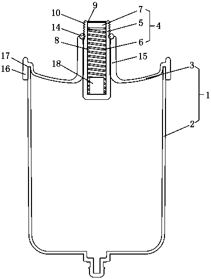
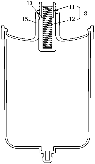
[0020] see figure 1 , the present invention provides a self-priming pressurized pressure tank, including a tank body 1, the tank body 1 includes a shell 2 and a cover 3, the shell 2 and the cover 3 are made of plastic, the cover The center of 3 is provided with hydraulic buffer device 4, and described hydraulic buffer device 4 comprises main body 5, spring 6 and buffer block 7, and the material of described main body 5 and spring 6 is stainless steel, and the material of stainless steel can play anticorrosion The free end of the main body 5 is recessed axially inward to form a chute 8, the buffer block 7 is placed in the chute 8 and the buffer block 7 can move up and down in the chute 8 in the axial direction; The outer wall of the buffer block 7 is matched and attached to the groove wall of the chute 8; the upper edge of the chute 8 exten...


PUM


Abstract

The invention discloses a self-sucking boosting pressure tank. The self-sucking boosting pressure tank comprises a tank body. The tank body comprises a shell and a cover. The shell and the cover are plastic. A water pressure buffering device is arranged at the center of the cover, and comprises a main body, a spring and a buffering block. The main body and the spring are made of stainless steel. The free end of the main body is recessed inwardly along the axial direction to form a sliding groove. The buffering block is arranged in the sliding groove, and can move up and down in the sliding groove along the axial direction. The outer wall of the buffering block is fittingly attached to the wall of the sliding groove. The upper edge of the sliding groove extends towards the center along theinner wall to form an annular riveting block. By the annular riveting block, the buffering block is enabled to be located in the sliding groove constantly. The bottom end of the spring is abutted against the bottom of the sliding groove. The top end of the spring is abutted against the bottom surface of the buffering block. The self-sucking boosting pressure tank has the advantages that the structure of the pressure tank becomes simple, the manufacture cost is reduced, and the good buffering effect is achieved.

Description

technical field [0001] The invention relates to a pressure tank, in particular to a self-priming pressurized pressure tank. Background technique [0002] The pressure tank is used in a closed water circulation system to balance the water volume and pressure, avoiding frequent opening of the safety valve and frequent replenishment of the automatic water replenishment valve. The pressure tank not only plays the role of containing the expansion water, but also plays the role of a water replenishment tank. Existing pressure tanks usually include a tank body and an air bag placed in the tank body. The material of the tank body is metal. The front end of the tank body has a screw joint, and the rear end has an air injection port. Nitrogen is poured into the tank to obtain a large volume to accommodate the expansion water. The high and low pressure pressure tanks can use their own pressure in parallel to replenish water to the pressure stabilization system. The pressure tank opera...

Claims


Application Information

Patent Timeline
Patent Type & Authority Applications(China)
IPC IPC(8): E03B11/00
CPCE03B11/00
Inventor 朱林达
Owner 朱林达
Learn More