Film tearing machine

A film machine and machine body technology, applied in the field of film tearing machine, can solve the problems of not improving the qualified rate of tearing film products, affecting work efficiency, reducing the service life of the machine body, etc., so as to improve the success rate and work efficiency of tearing film, and improve the product quality. Qualification rate and the effect of increasing work efficiency

Pending Publication Date: 2018-07-24
SHENZHEN NUOFENG OPTOELECTRONICS EQUIP
View PDF8 Cites 2 Cited by
  • Summary
  • Abstract
  • Description
  • Claims
  • Application Information

AI Technical Summary

Problems solved by technology

[0003] However, the film tearing machines currently on the market have complex structures and single functions. They cannot absorb and concentrate the dust particles generated by the film tearing machine during the film tearing process, and cannot provide a good working environment for film tearing. At the same time, dust pollution will also It affects the efficiency of tearing the film. In addition, air bubbles will be generated during the tearing process, which will affect the appearance of the film after tearing. The stability of the work, when the body is in a shaking state for a long time, will reduce the service life of the body, and cannot guarantee the normal progress of the tearing film. Without the PT100 temperature sensor, heating device and the first fan, the success rate of tearing the film cannot be improved and Efficiency of tearing film

Method used


Image

  • Film tearing machine
  • Film tearing machine
  • Film tearing machine

Examples


Embodiment

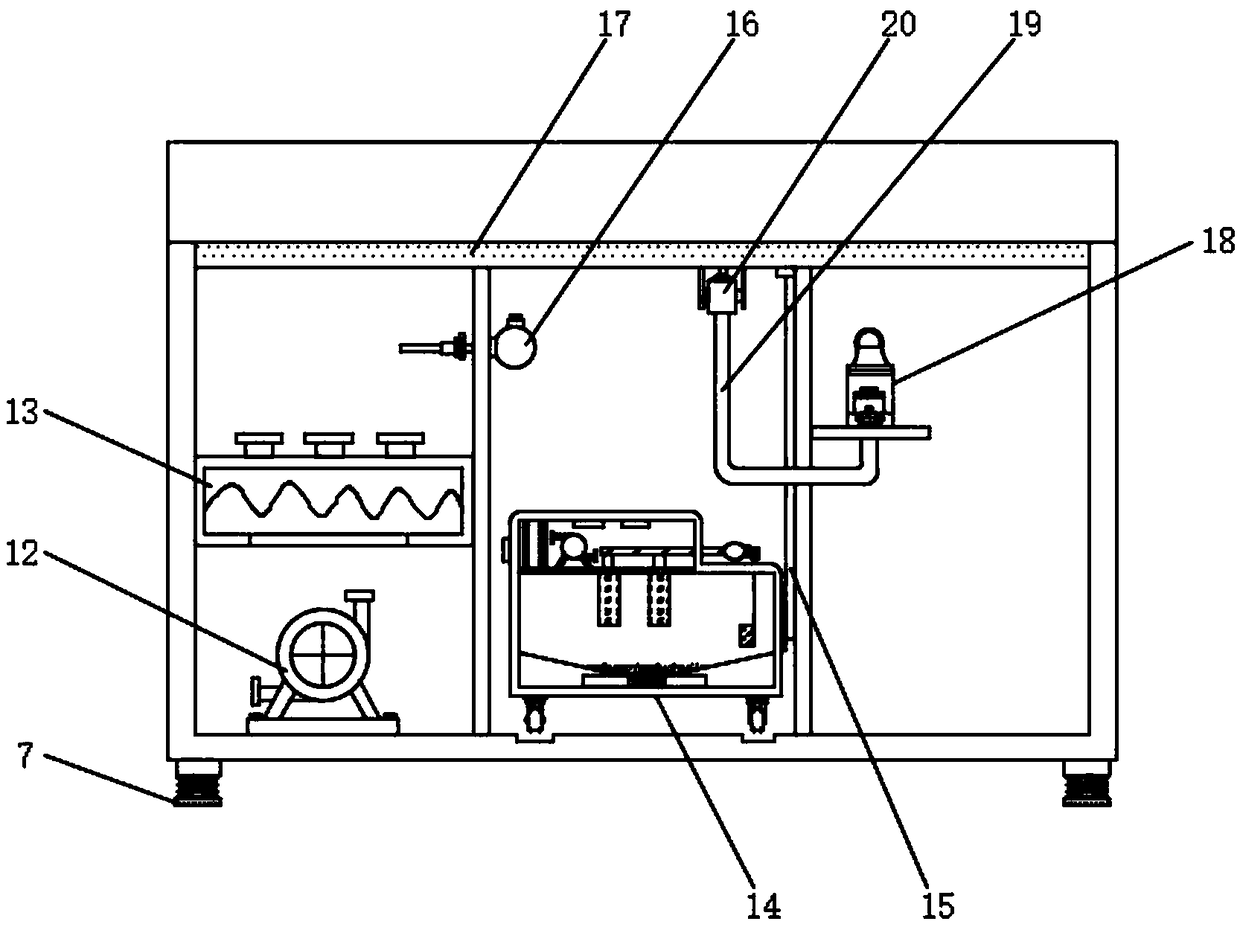
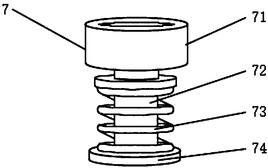
[0029] Example: refer to Figure 1-6 , the present invention provides a technical solution, a film tearing machine, including a body 1, a partition 2 is arranged on the top of the body 1 near the middle, and a first release is arranged on the side of the top of the body 1 near the partition 2 Material shaft 3, the top of the body 1 is provided with a second discharge shaft 4 near the other side of the partition 2, the top of the body 1 is provided with a first material guide rod 5 near the side of the first discharge shaft 3, and the body A second material guide rod 6 is arranged on the side close to the second discharge shaft 4 above 1, a buffer device 7 is fixedly installed on the bottom end of the body 1, and a ventilation plate 17 is connected above the body 1 near the lower end of the partition plate 2 , the middle part of the body 1 is provided with a second working chamber 9, and the side of the middle part of the body 1 close to the second working chamber 9 is provided...


PUM


Abstract

The invention discloses a film tearing machine. The film tearing machine comprises a machine body; a partition plate is arranged above the machine body and near the middle position; a first discharging shaft is arranged above the machine body and near one side of the partition plate; a second discharging shaft is arranged above the machine body and near the other side of the partition plate; a first material guide rod is arranged above the machine body and near one side of the first discharging shaft; and a second material guide rod is arranged above the machine body and near one side of the second discharging shaft. An atomizer and an atomizing spray head are provided, bubbles generate in the film tearing process and the bubbles are reduced through the action of the atomizer and the atomizing spray head, so that beautiful appearance after the film is torn is enhanced and the qualification rate of the film-tearing products is increased; a buffer device is provided, so that the work stability of the machine body in the film-tearing process can be guaranteed and the fact that the film can be torn normally is guaranteed; and a PT100 temperature sensor, a heating device and a fan are provided, so that the success rate of film tearing is increased, the working efficiency of film tearing is improved and the production cost is reduced.

Description

technical field [0001] The invention relates to the technical field of film tearing machines, in particular to a film tearing machine. Background technique [0002] In industrial production, some products need to be stored. During storage, the product needs to be protected by a film. When in use, the film on the product needs to be torn off, and then the next step is performed. When tearing the film, a film tearing machine is required. The film machine can quickly tear off the film. The film tearing machine is mainly used for glass products and optical film materials, and is protected by the tearing film of the film tearing machine. [0003] However, the film tearing machines currently on the market have complex structures and single functions. They cannot absorb and concentrate the dust particles generated by the film tearing machine during the film tearing process, and cannot provide a good working environment for film tearing. At the same time, dust pollution will also I...

Claims


Application Information

Patent Timeline
IPC IPC(8): B65B69/00
CPCB65B69/00B65B69/0066
Inventor 许永洲李欣华
Owner SHENZHEN NUOFENG OPTOELECTRONICS EQUIP
Why Eureka
Try Eureka