


Quick Research
Generate reliable direction feasibility study reports for your R&D in just a few steps.

Technical Q&A
Discover and master advanced knowledge NOW. Basics, ideas, possibilities, all at once.

Find Solutions
As an expert in R&D theories, this can generate solutions to your technical problems instantly.

Evaluate Feasibility
Analyze your overall solution with one click, know your potential R&D risks in advance.

Monitor Landscape
Get weekly tech updates, stay abreast of the latest tech innovations and key insights.
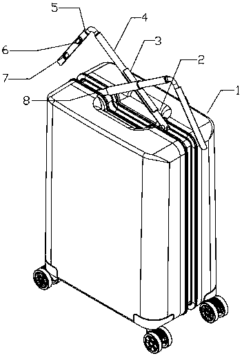
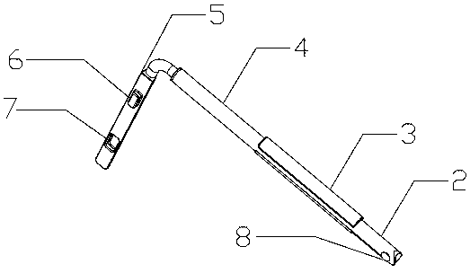
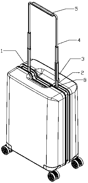
Suitcase with rotatable retractable draw bar
A technology for telescopic drawbars and suitcases, applied in the field of travel case products, can solve the problems of shortening the service life of drawbars, the arc of the drawbars, and the blockage of drawbars, so as to reduce the length and the number of sections, reduce the weight of drawbars, and reduce production costs.
- Summary
- Abstract
- Description
- Claims
- Application Information
AI Technical Summary
Problems solved by technology
Method used
Image

Examples
Embodiment Construction
[0015] In order to make the objectives, technical solutions and advantages of the present invention clearer, the present invention will be further described in detail below with reference to the accompanying drawings and embodiments. It should be understood that the specific embodiments described herein are only used to explain the present invention, but not to limit the present invention. like Figure 1-Figure 3 As shown in the figure, a travel case with a rotatable telescopic pull rod includes a horizontally arranged box body 1, a box body groove is set in the middle of the box body 1 above the box body 1, and the rotating shaft 8 is connected by bolts It is fixed at the groove part of the box body, the tail end of the outer tube 2 is embedded in the box body groove on the box body 1 through the rotating shaft 8, the inner tube 4 is embedded in the outer tube 2, and the inner tube 4 can be Slide along the axial direction of the outer tube 2, one end of the inner tube 4 is c...
PUM
 Abstract
Description
Claims
Application Information
 - R&D Engineer
- R&D Manager
- IP Professional
- Industry Leading Data Capabilities
- Powerful AI technology
- Patent DNA Extraction
Browse by: Latest US Patents, China's latest patents, Technical Efficacy Thesaurus, Application Domain, Technology Topic, Popular Technical Reports.
© 2024 PatSnap. All rights reserved.Legal|Privacy policy|Modern Slavery Act Transparency Statement|Sitemap|About US| Contact US: help@patsnap.com