
Pressure relief valve

A pressure relief valve and pressure relief technology, applied in the direction of safety valves, balance valves, valve devices, etc., can solve the problems of complicated installation, complex and cumbersome structure of pressure relief valves, and difficulty in processing and manufacturing, so as to achieve convenient installation and industrialization , the overall structure is simple

Pending Publication Date: 2018-07-20
无锡市金帝旸金属科技有限公司
View PDF1 Cites 2 Cited by
  • Summary
  • Abstract
  • Description
  • Claims
  • Application Information

AI Technical Summary

Problems solved by technology

[0004] This kind of pressure relief valve has a complex and cumbersome structure, complicated installation, and is not easy to process and manufacture.

Method used


Image

  • Pressure relief valve
  • Pressure relief valve
  • Pressure relief valve

Examples


Embodiment Construction

[0034] 以下结合附图对本发明作进一步详细说明。

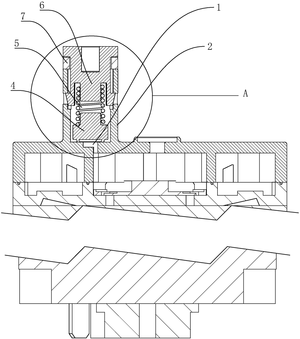
[0035] 一种泄压阀2,如 figure 1 所示,包括泄压口1和正对泄压口1设置的泄压阀2,所述泄压阀2包括泄压底座3、密封件4、弹性件5和卡接件6;泄压底座3内部设有一圆形空腔31,空腔31一端与泄压口1相连通,另一端与卡接件6卡接,卡接件6与泄压底座3之间留有一定用于出气的间隙,密封件4位于空腔31内且与泄压口1相互贴合,弹性件5位于密封件4和卡接件6之间,弹性件5抵紧密封件4和卡接件6。

[0036] 在泄压过程中,气体从泄压口1进入空腔31时,抵触到密封件4上,随着气体的增大,密封件4向上运动推动弹性件5,密封件4抵触到卡接件 6停止运动,气体从空腔31与卡扣61之间的缝隙处流出,达到泄压的目的;当气体压力减小时,密封件4在弹性件5的弹性下向下运动,封住泄压 port 1.

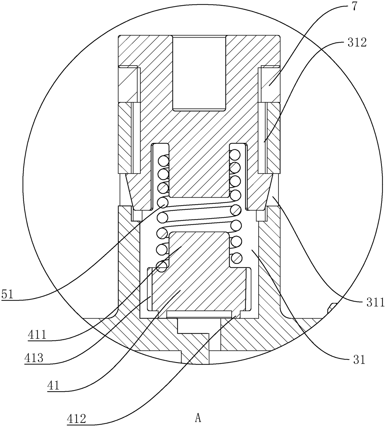
[0037] Such as figure 2 with image 3 所示,弹性件5为弹簧51,密封件4为一密封帽41,卡接件6为一卡扣61。

[0038] 密封帽41为一圆柱,圆柱一端面与泄压口1贴合,另一端面上设有一凸块411,凸块411与弹簧51卡接,密封帽41与泄压底座3的空腔31之间留有一定间隙。

[0039] 卡扣61包括本体611、弹性卡钩612、阻挡块613和限位环614,本体611为一圆柱,本体611一端面延伸有一阻挡块613,另一端面设有两个弹性卡钩612,两个卡爪之间开有限位环614,限位环614与弹簧51连接。

[0040] 泄压底座3侧壁开有与弹性卡钩612相应的卡孔311,泄压底座3背离泄压口1的一侧设有导向槽312,导向槽312与卡孔311相互连通,所述卡爪沿着导向槽312线性运动,与卡孔311相互卡接。

[0041] 安装时,先把密封帽41放入空腔31,套上弹簧51,再把卡扣61的弹性卡勾压缩沿着导向槽312向下滑动,使弹性卡钩612和卡孔311相互卡接 ,finish installation.

[0042] 卡接件6与泄压底座3的间隙之间设有海绵消音环7,消音环7一端抵触泄压底座3端面,另一端抵触阻挡块613的端面。

[0043] 密封帽41贴合泄压口1的一侧设有凸环412,凸环412的直径大于密封口的直径。密封帽4...


PUM


Abstract

The invention discloses a pressure relief valve. The pressure relief valve is compact in structure and convenient to install. The pressure relief valve is characterized by comprising a pressure reliefopening and a pressure relief valve body opposite to the pressure relief opening, wherein the pressure relief valve body comprises a pressure relief base, a seal piece, an elastic piece and a clampedconnection piece, a round cavity is formed in the pressure relief base, one end of the cavity communicates with the pressure relief opening, the other end of the cavity is connected with the clampedconnection piece in a clamped manner, a certain interval for gas exhaust is reserved between the clamped connection piece and the pressure relief base, the seal piece is located in the cavity, the seal piece and the pressure relief opening are attached to each other, the elastic piece is located between the seal piece and the clamped connection piece, and the elastic piece tightly abuts against the seal piece and the clamped connection piece. In the pressure relief process, when gas enters the cavity from the pressure relief opening, the gas abuts against the seal piece in a contact manner, along with increase of the volume of the gas, the seal piece moves upwards to push the elastic piece, the seal piece stops movement when abutting against the clamped connection piece in a contact manner, the gas flows out from the gap between the cavity and a buckle, and the pressure relief purpose is achieved.

Description

technical field [0001] 本发明涉及汽车阀门技术领域,特别涉及一种泄压阀。 Background technique [0002] 泄压阀是在调节汽车座椅时,控制座椅前后移动的一种阀门。 [0003] 目前,公开号为CN203718065U的中国专利公开了一种泄压阀,它包括第一控制腔和第二控制腔, 阀体底部设有与第一控制腔连通的进气口, 在阀体的侧部设有与第二控制腔连通的第一出气口和第二出气口, 第一控制腔和第二控制腔通过下端部的连接通道连通, 第一控制腔和进气口之间形成有环形口,环形口内径小于第一控制腔和进气口的内径, 第一控制腔设有位于环形口上方的固定座, 固定座上穿有推杆, 推杆向下延伸至进气口, 推杆外径小于环形口的内径, 且推杆和环形口之间形成有间隙, 推杆下端延伸至进气口内, 在推杆下端设有密封塞。 [0004] 这种泄压阀结构复杂繁琐,安装复杂,不易于加工制造。 Contents of the invention [0005] 本发明的目的是提供一种泄压阀,其具有结构紧凑,安装方便的优点。 [0006] Above-mentioned technical purpose of the present invention is achieved through the following technical solutions: [0007] 一种泄压阀,包括泄压口和正对泄压口设置的泄压阀,所述泄压阀包括泄压底座、密封件、弹性件和卡接件;泄压底座内部设有一圆形空腔,空腔一端与泄压口相连通,另一端与卡接件卡接,所述卡接件与泄压底座之间留有一定用于出气的间隙,所述密封件位于空腔内且与泄压口相互贴合,弹性件位于密封件和卡接件之间,弹性件抵紧密封件和卡接件。 [0008] 通过采用上述技术方案,在泄压过程中,气体从泄压口进入空腔时,抵触到密封件上,随着气体的增大,密封件向上运动推动弹性件,密封件抵触到卡接件停止运动,气体从空腔与卡扣之间的缝隙处流出,达到泄压的目的; [0009] 当气体压力减小时,密封件在弹性件的弹性下向下运动,封住泄压口,整体结构简单,紧凑,便于产业化。 [0010] 优选的:所述弹性件为弹簧,弹簧一端抵触凸块,另一端抵触卡接件。 [0011]...

Claims


Application Information

Patent Timeline
Patent Type & Authority Applications(China)
IPC IPC(8): F16K17/04F16K17/164
CPCF16K17/04F16K17/164
Inventor 尹祖军
Owner 无锡市金帝旸金属科技有限公司
Learn More