
Vehicle license plate snow removing device

A technology for license plates and vehicles, which is applied in the field of snow removal devices and vehicle license plate snow removal devices, and can solve the problems that vehicle license plates cannot be automatically recognized normally

Pending Publication Date: 2018-07-20
WUXI PEOPLES HOSPITAL
View PDF0 Cites 3 Cited by
  • Summary
  • Abstract
  • Description
  • Claims
  • Application Information

AI Technical Summary

Problems solved by technology

[0004] The purpose of the present invention is to solve the problem that the vehicle license plate cannot be recognized automatically due to snow accumulation, and to provide a vehicle license plate snow removal device, which can quickly remove the snow on the vehicle license plate by using the blower to power up and assist heating, and help to automatically identify the vehicle license plate. Identify vehicle systems operating normally

Method used


Image

  • Vehicle license plate snow removing device
  • Vehicle license plate snow removing device
  • Vehicle license plate snow removing device

Examples


Embodiment 1

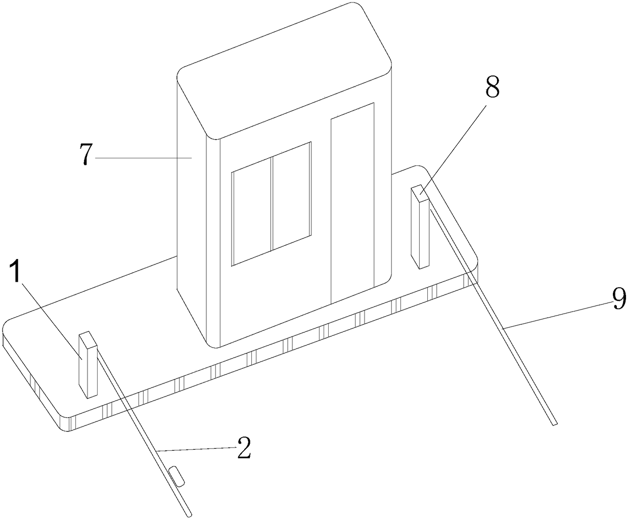
[0023] In embodiment 1, taking the induction device as the induction probe 5 as an example, as figure 1 As shown, the automatic vehicle identification system includes a toll booth 7, a license plate recognition probe 8 positioned on one side of the toll booth 7, and a lift bar 9 connected to the license plate recognition probe 8, and the snow removal device is fixed on the In front of the automatic vehicle identification system, and the snow removal device is located outside the distance that the license plate recognition probe 8 can recognize;

[0024] The J&J ARMY model selected in this embodiment 1 is the induction probe 5 of JT18-5MNO, and the sensing distance of the induction probe 5 is about 4m;

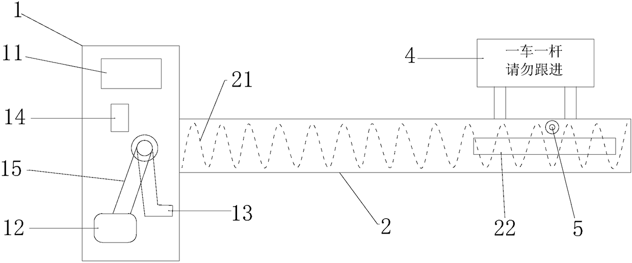
[0025] Such as figure 2 with Figure 4 As shown, the snow removal device includes a control box 1, an undercarriage 2 and an induction probe 5. A control module 11 and a motor 12 connected with the control module 11 are arranged in the control box 1. The motor 12 is connecte...

Embodiment 2

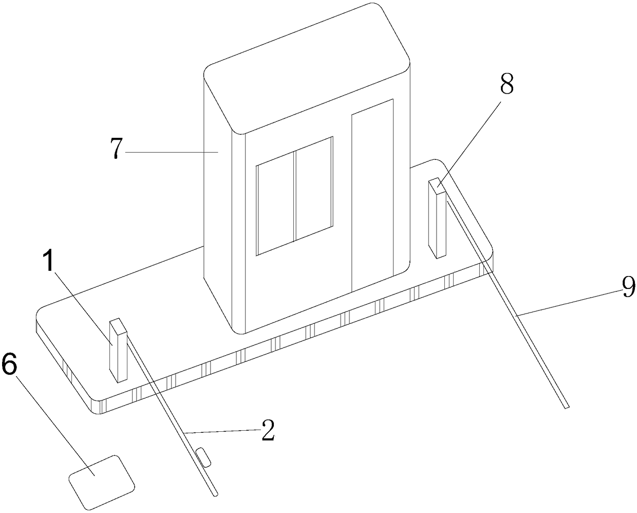
[0027] In embodiment 2, taking the induction device as the ground induction coil 6 as an example, as image 3 As shown, the automatic vehicle identification system includes a toll booth 7, a license plate recognition probe 8 located on one side of the toll booth 7, and a lift bar 9 connected to the license plate recognition probe 8, and the snow removal device is fixed to the vehicle automatic by anchor bolts. The front of the recognition system, and the snow removal device is located outside the distance that the license plate recognition probe 8 can identify; the snow removal device includes a control box 1, a landing gear 2 connected to the control box 1, and a ground surface about 2 m ahead of the landing gear 2 Buried ground sense coil 6;

[0028] The structure of the control box 1 and the landing gear 2 of the snow removal device in the present embodiment 2 is identical with the present embodiment 1;

[0029] In this embodiment 2, the selected manufacturer is Dexiang, a...


PUM


Abstract

The invention belongs to the technical field of vehicle license plate recognition, and relates to a vehicle license plate snow removing device. The vehicle license plate snow removing device is characterized in that a snow removing device body is fixed in front of an automatic vehicle identification system by a foundation bolt, and the snow removing device comprises a control box and a landing frame, a control module and a motor connected with the control box are arranged in the control box, and the motor is connected with one end of the landing frame in a transmission mode. A heating wire isarranged in the landing frame, an air blower is arranged on the back face of the control box, the air blower and the heating wire are connected with the control module, an air outlet of the air blowercommunicates with the interior space of the landing frame, and an air outlet is formed in the other end of the landing frame. An induction device is connected with the control module in the control box. According to the vehicle license plate snow removing device, the heating wire is heated by the air blower, snow on the vehicle license plate can be removed quickly, the automatic vehicle identification system can operate normally, and the vehicle license plate snow removing device is convenient and fast, and time and labor are saved.

Description

technical field [0001] The invention relates to a snow removal device, in particular to a vehicle license plate snow removal device, which belongs to the technical field of vehicle license plate recognition. Background technique [0002] Whether the current car parks in the parking lot or enters the expressway, the admission parking system and the toll system on the expressway mostly adopt the method of automatic recognition of the vehicle license plate to collect fees. Usually, the recognition rate can reach more than 95%. However, in snowy days, a large amount of snow will accumulate on the vehicle license plate, which will cause the automatic identification system to fail to recognize the license plate of the vehicle, which will affect the normal charging, and then affect the dredging of vehicles in the parking lot and the normal passage of the expressway. [0003] In order to solve this problem at present, it is very inconvenient, time-consuming and labor-intensive to ma...

Claims


Application Information

Patent Timeline
IPC IPC(8): E01F13/06F24H3/04F24H9/18F24H9/20
CPCF24H3/0429F24H9/1863F24H9/2071E01F13/06
Inventor 卢建雄
Owner WUXI PEOPLES HOSPITAL
Learn More