Power generation apparatus and control method thereof

A power generation device and control chip technology, which is applied in the direction of electromechanical devices, cooling/ventilation devices, and control/drive circuits, etc., can solve the problems of generator energy consumption, failure, etc., to achieve the improvement of electric energy and energy saving, and reduce the reaction force Effect

Pending Publication Date: 2018-07-17
高彰
View PDF2 Cites 1 Cited by
  • Summary
  • Abstract
  • Description
  • Claims
  • Application Information

AI Technical Summary

Problems solved by technology

[0004] In fact, during the power generation process, the interaction between the generator winding and the magnet is one of the main reasons for the energy consumption of the generator. How to reduce the above-mentioned interaction and achieve high-efficiency operation of the power generation device has not yet been related. Research

Method used


Image

  • Power generation apparatus and control method thereof
  • Power generation apparatus and control method thereof
  • Power generation apparatus and control method thereof

Examples


Embodiment 1

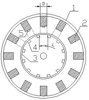
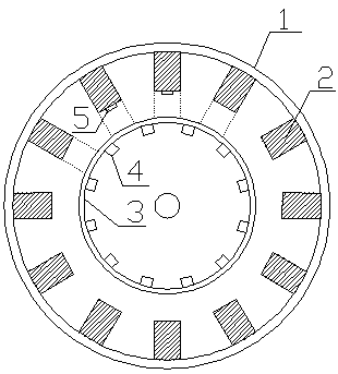
[0047] As shown in 1, a power generating device includes a winding base 1, a winding 2 disposed on the winding base 1, a magnet base 3, a magnet 4 disposed on the magnet base 3, and a magnet 4 disposed on the winding 2 for A position sensor 5 and a control circuit that perceives the position of the magnet 4, wherein: the diameter D of the winding 2 is less than the distance L between adjacent magnets 4; When the magnet 4 and the winding 2 move relatively, the control circuit conducts the winding 2 when the winding 2 is located between two adjacent magnets 4, and controls the discharge of the winding 2 to the outside. The position during discharge is as follows: figure 2 shown.

[0048] Specifically, the distance L is the arc length between two adjacent magnets.

[0049] It should be noted, figure 2The discharge of the middle winding 2 generates an induced magnetic field. Since the induced magnetic field is far away from the magnet 4 and the magnetic poles of the magnetic f...

Embodiment 2

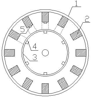
[0054] Such as image 3 As shown, on the basis of the first embodiment, the magnets 4 in this implementation are evenly arranged, and the number of the magnets 4 is six. When the magnet 4 and the winding 2 move relatively, the control circuit conducts the winding 2 and controls the winding 2 to discharge to the outside when the winding 2 is located between two adjacent magnets 4 .

Embodiment 3

[0056] Such as Figure 4 As shown, on the basis of Embodiments 1 and 2, the magnets 4 in this implementation are arranged non-uniformly, and the number of magnets 4 is two.

[0057] At this time, each winding 2 is provided with a position sensor 5 .

[0058] When the magnet 4 and the winding 2 move relatively, the control circuit conducts the winding 2 and controls the corresponding winding 2 to discharge to the outside when the winding 2 is located between two adjacent magnets 4 .


PUM


Abstract

The invention discloses a power generation apparatus and a control method thereof, and relates to the technical field of electromagnetic induction power generation. The power generation apparatus comprises a winding base, windings arranged on the winding base, a magnet base, magnets arranged on the magnet base, a position sensor arranged on the windings for sensing the magnet positions, and a control circuit, wherein the diameters of the windings are smaller than the distance between adjacent magnets; the control circuit is connected with the position sensor; and according to the control method of the power generation apparatus, the winding is conducted when the corresponding winding is positioned between two adjacent magnets based on the relative position of the magnet and the corresponding winding so as to control the winding to perform pulse discharge outwards. By virtue of the power supply apparatus provided by the invention, by changing the dimensions of the windings and the magnets and the discharging mode, the reactive force between the power generation windings and the magnets is lowered, and the power for driving a generator is lowered, thereby achieving high efficiency power generation of the generator and realizing energy conservation and emission reduction.

Description

technical field [0001] The invention relates to the technical field of power generation, in particular to a high-efficiency energy-saving power generation device and a control method thereof. Background technique [0002] Generator is one of the main equipments for electric energy production. The existing generator technology mainly generates electric energy by cutting the power generation winding and the magnetic field, and improving the efficiency of the generator is mainly to improve the power generation efficiency and energy saving of the generator by steam flow, improving the excitation winding, and improving the utilization rate of the permanent magnet. [0003] Patent No.: 201510765665.6, Invention Name: Radially Distributed Three-phase Disk Type Transverse Flux Permanent Magnet Generator; Patent No.: 201511030286.9, Invention Name: Induction Capacitor Generator. The above patent documents all refer to the methods mentioned above in the documents of the present inven...

Claims


Application Information

Patent Timeline
Patent Type & Authority Applications(China)
IPC IPC(8): H02K29/08H02K29/10H02K11/33H02P9/30
CPCH02K11/33H02K29/08H02K29/10H02P9/30H02K9/02H02P6/15
Inventor 不公告发明人
Owner 高彰
Why Eureka
Try Eureka