
Automatic material taking device of injection molding machine

An automatic reclaiming and injection molding machine technology, applied in the field of injection molding machines, can solve problems affecting production efficiency, injection molded product mixed cavities, and labor intensity of workers, etc., to achieve the effects of reducing labor intensity, preventing cavities mixing, and improving production efficiency

Pending Publication Date: 2018-07-17
江苏顺航电子科技有限公司
View PDF0 Cites 1 Cited by
  • Summary
  • Abstract
  • Description
  • Claims
  • Application Information

AI Technical Summary

Problems solved by technology

[0005] The disadvantage of the above-mentioned retrieving device of the injection molding machine is that the injection molded product is easy to block the opening of the corresponding material bag when it falls into the corresponding material bag on the lower material distribution rack under the action of its own weight. Subsequent transported injection molding products will not be able to enter the corresponding material bag, resulting in subsequent transported injection molded products will slide into other material bags on the material distribution rack along the material distribution rack, resulting in mixed cavities of injection molded products. Manually re-segregate the injection molded products in each material bag on the material distribution rack, not only the labor intensity of the workers is high, but also the production efficiency is affected

Method used


Image

  • Automatic material taking device of injection molding machine
  • Automatic material taking device of injection molding machine

Examples


Embodiment Construction

[0015] The present invention will be further described below in conjunction with the accompanying drawings and specific embodiments.

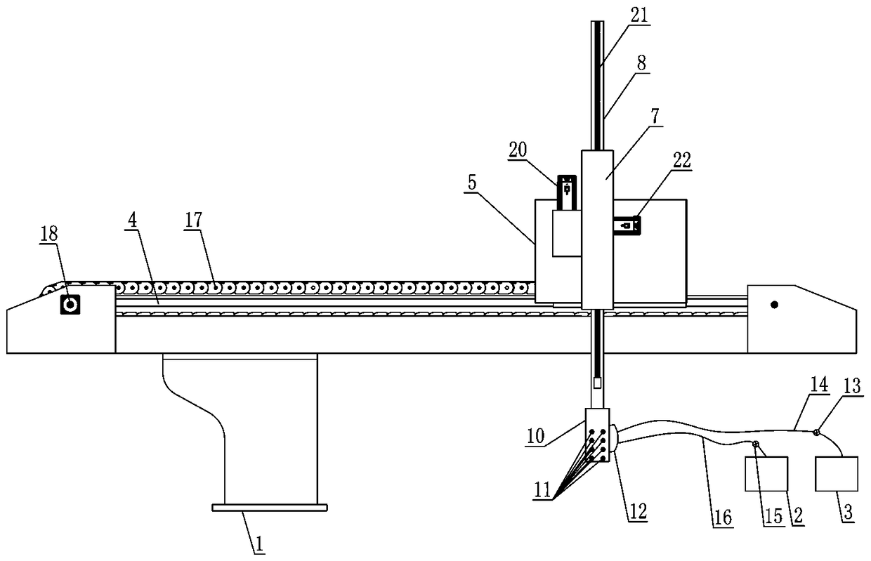
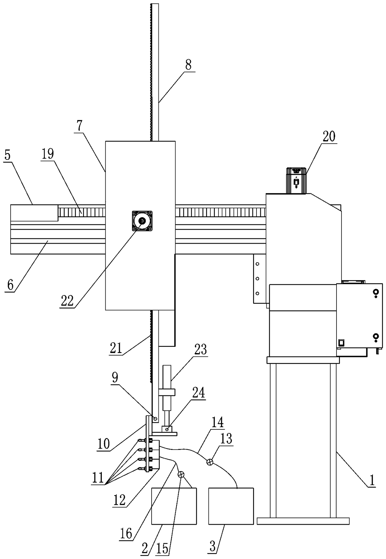
[0016] Such as figure 1 , figure 2 As shown, the automatic retrieving device for an injection molding machine includes a frame 1, a negative pressure air source 2 and a positive pressure air source 3, and the frame 1 is provided with a first guide rail composed of several left and right direction A guide rail group 4, on the first guide rail group 4, a first mobile frame 5 is slidably arranged, and the first mobile frame 5 is driven by a first driving mechanism to move left and right along the first guide rail group 4, and the first mobile frame 5 is provided with The second guide rail group 6 composed of several second guide rails moving forward and backward, on the second guide rail group 6, a second moving frame 7 is slidably arranged, and the second moving frame 7 is driven by the second driving mechanism along the second guide rail group...


PUM


Abstract

The invention discloses an automatic material taking device of an injection molding machine. The automatic material taking device comprises a machine frame, a negative pressure air source and a positive pressure air source, wherein a first guide rail set is arranged in the machine frame, a first movable frame driven by a first driving mechanism to move is arranged on the first guide rail set, anda second guide rail set is arranged on the first movable frame; a second movable frame driven by a second driving mechanism to move is arranged on the second guide rail set in a sliding mode, a vertical guide rail set is arranged on the second movable frame, and a longitudinal movable frame driven by a third driving mechanism to move is arranged on the vertical guide rail set in a sliding mode; anoverturning frame is hinged to the bottom of the longitudinal movable frame through a rotating shaft, and the overturning frame is driven by a fourth driving mechanism to overturn around the rotatingshaft; and a plurality of nozzles corresponding to material bags on a material distribution frame are arranged on the overturning frame, all the nozzles communicate with a main air pipe, and the mainair pipe communicates with the positive pressure air source through an air blowing air pipe with an air blowing valve, and meanwhile communicates with the negative pressure air source through an airsuction air pipe with an air suction valve. The automatic material taking device of an injection molding machine has the advantages of being high in production efficiency and low in labor intensity ofworkers.

Description

technical field [0001] The invention relates to the technical field of injection molding machines, in particular to an automatic feeding device for injection molding machines. Background technique [0002] The feeding device of the injection molding machine is an important part of the injection molding machine. It is mainly used to take out different types of injection products from the fixed mold and send them to the outside of the injection molding machine. in the respective corresponding material bags on the material rack. The structure of the currently used injection molding machine reclaiming device is: including a frame and a negative pressure air source, a first guide rail group consisting of a number of left and right first guide rails is arranged in the frame, sliding on the first guide rail group A first moving frame is provided, and the first moving frame is driven by the first driving mechanism to move left and right along the first guide rail group. A second m...

Claims


Application Information

Patent Timeline
IPC IPC(8): B29C45/42B29C45/17
CPCB29C45/1769B29C45/42B29C45/4225B29C2045/177B29C2045/4233
Inventor 陈小逸杨作磊李道杏梅晶晶
Owner 江苏顺航电子科技有限公司
Learn More