
a hydraulic device

A technology of hydraulic device and pressure plate, applied in the field of hydraulic device, can solve the problems of unbalanced force of hydraulic support device and shortened service life, and achieve the effects of timely adjustment process, increased stability and prolonged service life

Active Publication Date: 2019-06-28
CHONGQING WEIQING HYDRAULIC MACHINERY CO LTD
View PDF8 Cites 0 Cited by
  • Summary
  • Abstract
  • Description
  • Claims
  • Application Information

AI Technical Summary

Problems solved by technology

[0006] The purpose of the present invention is to provide a hydraulic device to solve the problem of shortened service life of the hydraulic support device due to unbalanced force

Method used


Image

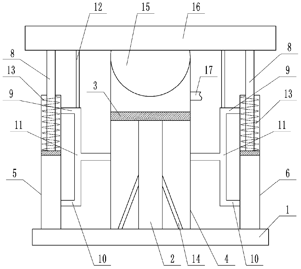
  • a hydraulic device
  • a hydraulic device

Examples


Embodiment Construction

[0020] The present invention will be described in further detail below by means of specific embodiments:

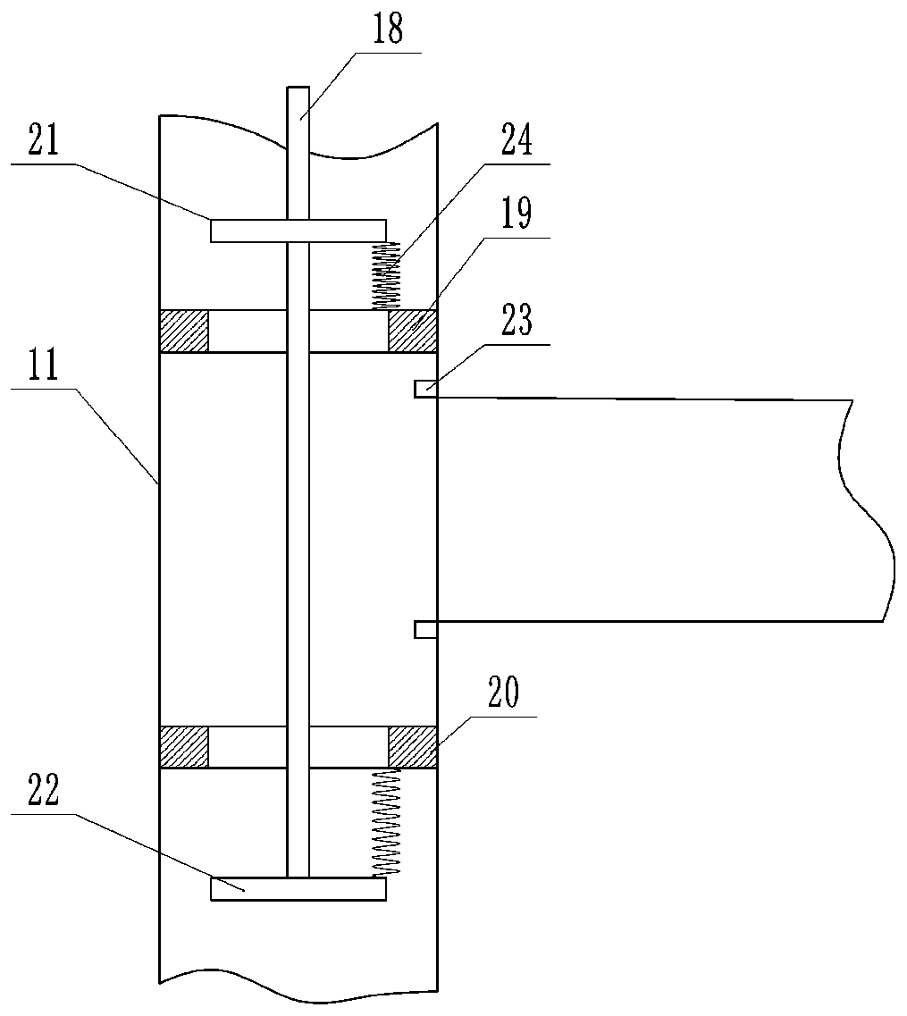
[0021] The reference signs in the accompanying drawings include: base 1, large piston rod 2, large piston 3, first sleeve 4, left sleeve 5, right sleeve 6, small piston rod 8, upper pipe 9, lower pipe 10 , tee 11, support rod 12, second spring 13, ejector rod 14, support 15, support plate 16, oil inlet pipe 17, push rod 18, upper sealing plate 19, lower sealing plate 20, upper pressing plate 21, lower pressing plate 22, block 23, first spring 24.

[0022] Such as figure 1 As shown, a hydraulic device includes a base 1 and a first sleeve 4, a large piston rod 2 is welded in the middle of the base 1, a large piston 3 is connected to the upper end of the large piston rod 2, and the first sleeve 4 slides with the large piston 3 And sealed connection, the lower end of the first sleeve 4 is equipped with a fixed block to prevent the large piston 3 from falling off, the upper ...


PUM


Abstract

The invention belongs to the technical field of hydraulic equipment, and particularly discloses a hydraulic device. The hydraulic device comprises a base and a first sleeve. A big piston rod is arranged on the base. A big piston is arranged on the big piston rod. A second sleeve and a third sleeve are separately arranged on the two sides of the first sleeve. A hemispherical support which is rotatably connected with the first sleeve in a sealing mode is arranged at the upper end of the first sleeve. Sealing plates with sliding holes are arranged at the upper ends of the two sleeves correspondingly. A supporting plate is arranged on the support. The second sleeve and the third sleeve are each internally provided with a small piston and a small piston rod. An upper pipeline, a lower pipelineand a tee joint are arranged on each of the first sleeve and the second sleeve. Valves are arranged on the tee joints. Supporting rods are connected between the valves and the supporting plate. The first sleeve is connected with an oil pump through an oil inlet pipe. The hydraulic device is mainly used for supporting a weight, and the problem that the service life of a hydraulic supporting deviceis shortened due to unbalanced stress is solved.

Description

technical field [0001] The invention belongs to the technical field of hydraulic equipment, and specifically discloses a hydraulic device. Background technique [0002] A hydraulic press is a machine that uses liquid as a working medium to transfer energy to achieve various processes. In addition to being used for forging and forming, hydraulic presses can also be used for straightening, pressing, packaging, briquetting, pressing plates and supporting heavy objects. Hydraulic presses include hydraulic presses and hydraulic presses. [0003] When supporting equipment or objects with a large mass, a hydraulic support device is usually used. A general hydraulic support device has a hydraulic support system, so the strength of its support is greatly limited. [0004] In view of the above problems, Chinese patent CN107191429A discloses a hydraulic support device, including a support base plate, the center of the upper surface of the support base plate is provided with a main ho...

Claims


Application Information

Patent Timeline
Patent Type & Authority Patents(China)
IPC IPC(8): F15B15/14
CPCF15B15/1404F15B15/1423
Inventor 谷山品
Owner CHONGQING WEIQING HYDRAULIC MACHINERY CO LTD
Learn More