
Bonding fixture, bonding equipment and bonding method for micro-luminescence device

A bonding jig and micro-luminescence technology, applied in the manufacture of semiconductor devices, electrical components, semiconductor/solid-state devices, etc., can solve the problems of inability to meet, increase production requirements, and increase the difficulty of packaging and die bonding, and reduce the Production cost, the effect of improving production efficiency

Active Publication Date: 2022-02-22
HUBEI SANAN OPTOELECTRONICS CO LTD
View PDF5 Cites 0 Cited by
  • Summary
  • Abstract
  • Description
  • Claims
  • Application Information

AI Technical Summary

Problems solved by technology

[0003] Due to the relatively close spacing between Micro LED chips, the difficulty of packaging and die bonding has increased, and the existing bonding equipment has low efficiency and cannot meet the increasing production demand.

Method used


Image

  • Bonding fixture, bonding equipment and bonding method for micro-luminescence device
  • Bonding fixture, bonding equipment and bonding method for micro-luminescence device
  • Bonding fixture, bonding equipment and bonding method for micro-luminescence device

Examples


Embodiment Construction

[0036] Several specific embodiments of the present invention will be further described in detail below in conjunction with the accompanying drawings. But the following descriptions and illustrations about the embodiments do not constitute any limitation to the protection scope of the present invention.

[0037] It should be understood that the terminology used in the present invention is only for the purpose of describing specific embodiments, rather than limiting the present invention. It is further understood that when the terms "comprising" and "comprising" are used in the present invention, they are used to indicate the existence of stated features, integers, steps, components, and / or packages, without excluding one or more other features, Presence or addition of integers, steps, components, packages, and / or combinations thereof.

[0038] Unless otherwise defined, all terms (including technical terms and scientific terms) used in this invention have the same meaning as co...


PUM


Abstract

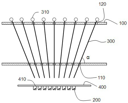
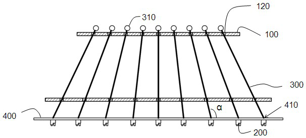
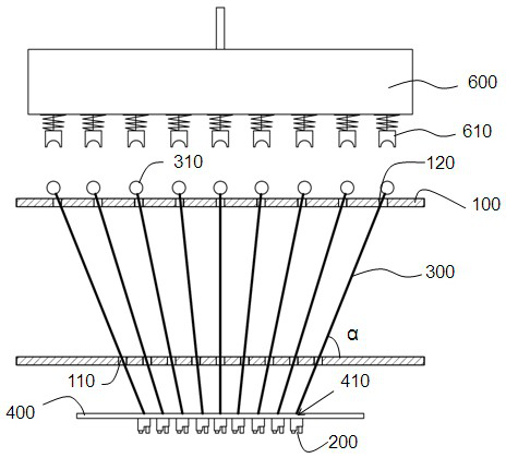
The present invention relates to a bonding fixture for a micro-luminescent device and a bonding method thereof. It is mainly composed of several porous plates, and each porous plate is provided with perforations to accommodate thimbles that are set according to the separation points of the micro-luminescent device to be bonded. , the two ends of the thimble protrude out of the jig, which is at the end of the micro-luminescent device to be bonded, which is the contact end corresponding to the point to be separated of the micro-luminescent device to be bonded, and at the end of the needle bed, it is the spring with the needle bed. At the contact end of the needle contact, each thimble has an appropriate slope according to the point to be separated. The perforated outer edge of the perforated plate at the end of the needle bed has a positioning hole for accommodating the end of the thimble, and the depth of the positioning hole is determined according to the slope of the thimble accommodated. Make sure that the thimbles at the end of the micro-luminescence device to be bonded have the same needle length, which has the effect of improving the stability of the bonding fixture and avoiding the unevenness of the bonding arrangement of the micro-luminescence device.

Description

technical field [0001] The invention relates to the field of packaging of micro-luminescence devices, in particular to the bonding technology of micro-luminescence devices. Background technique [0002] Micro LED is a miniaturized LED array structure with self-luminous display characteristics. Each pixel (pixel) can be individually addressed to drive light. The advantages include high brightness, low power consumption, small size, ultra-high resolution and color saturation etc. Compared with OLED technology, which is also a self-luminous display, Micro LED not only has higher efficiency and longer life, the material is not easily affected by the environment and is relatively stable, and can also avoid image sticking. [0003] Due to the relatively close spacing between Micro LED chips, the difficulty of packaging and die-bonding increases, and the existing bonding equipment is inefficient and unable to meet the increasing production demand. Contents of the invention [0...

Claims


Application Information

Patent Timeline
Patent Type & Authority Patents(China)
IPC IPC(8): H01L33/00H01L33/62
CPCH01L33/0095H01L33/62H01L2933/0066H01L21/6835H01L2221/68363H01L2224/7598H01L2224/7531H01L2224/75262H01L24/75H01L2224/97H01L2224/81224H01L24/81H01L2224/16227H01L2924/00012H01L2224/81
Inventor 徐宸科
Owner HUBEI SANAN OPTOELECTRONICS CO LTD
Learn More