
Driving method of touch display panel, driving circuit and touch display device

A technology of a touch display panel and a driving method, which is applied in static indicators, electrical digital data processing, input/output process of data processing, etc., and can solve the problem that the speed cannot meet the needs of touch display devices and the response of touch detection is slow and other issues to achieve the effect of improving the reporting rate and sensitivity and improving performance

Active Publication Date: 2018-07-06
KUSN INFOVISION OPTOELECTRONICS
View PDF11 Cites 7 Cited by
  • Summary
  • Abstract
  • Description
  • Claims
  • Application Information

AI Technical Summary

Problems solved by technology

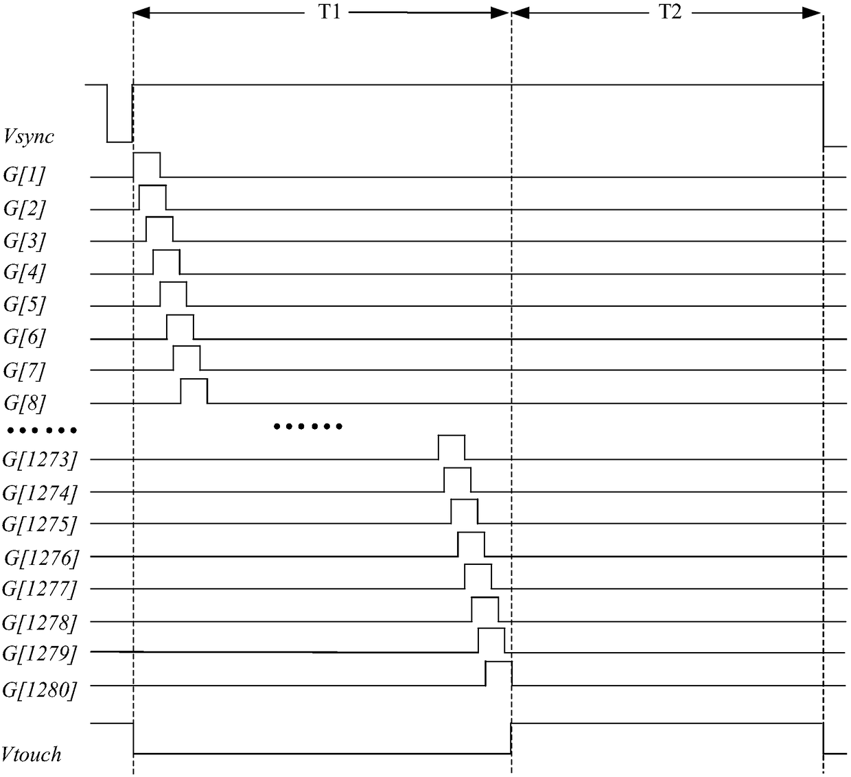
[0005] Some current touch display devices require the report frequency to be at least 120HZ, for example, a touch display device with an active capacitive touch pen. However, in the prior art, the screen display frequency is 60HZ, and the touch display The report frequency of the device is the same as the frequency displayed on the screen, which is also 60HZ, that is, in a frame of display screen, the touch display device only reports once, resulting in a very slow response of touch detection, and the speed of touch detection cannot meet the requirements. Demand for Touch Display Devices

Method used


Image

  • Driving method of touch display panel, driving circuit and touch display device
  • Driving method of touch display panel, driving circuit and touch display device
  • Driving method of touch display panel, driving circuit and touch display device

Examples


Embodiment Construction

[0024] Hereinafter, the present invention will be described in more detail with reference to the accompanying drawings. In the various figures, identical elements are indicated with similar reference numerals. For the sake of clarity, various parts in the drawings have not been drawn to scale. Also, some well-known parts may not be shown in the drawings.

[0025] In the following, many specific details of the present invention, such as structures, materials, dimensions, processes and techniques of components, are described for a clearer understanding of the present invention. However, the invention may be practiced without these specific details, as will be understood by those skilled in the art.

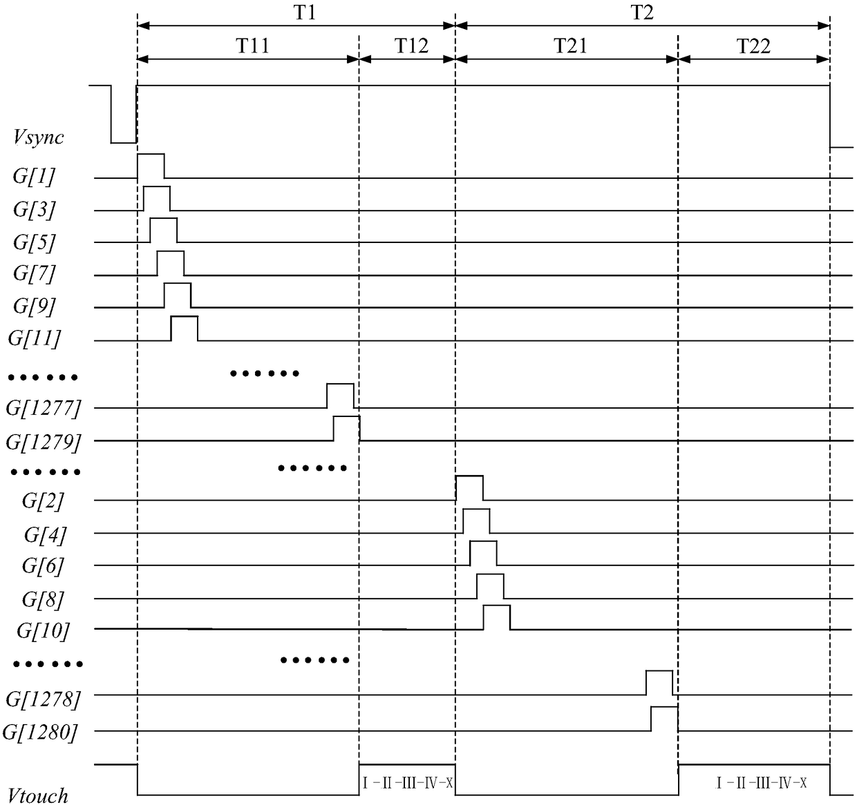
[0026] figure 2 A timing diagram illustrating a driving method of a touch display panel according to an embodiment of the present invention.

[0027] Such as figure 2 As shown, according to the driving method for a touch display panel provided by the present invention, the to...


PUM


Abstract

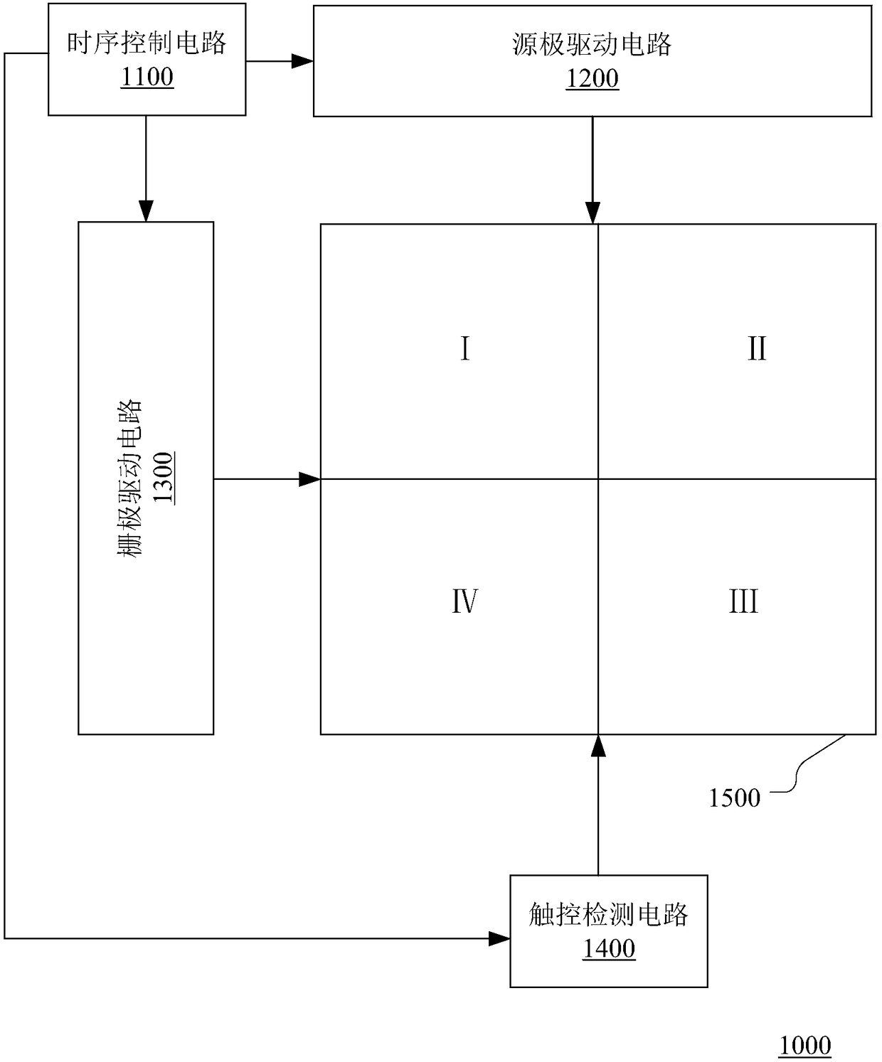
The invention discloses a driving method of a touch display panel, a driving circuit and a touch display device. The touch display panel comprises L rows of gate lines and M touch scanning regions, and both L and M are positive integers greater than 1. The driving method of the touch display panel includes the steps that each frame is at least divided into a first display sub-frame, a second display sub-frame, a first touch sub-frame and a second touch sub-frame; the L rows of gate lines are divided into first partial gate lines and second partial gate lines; in the first display sub-frames, the first partial gate lines are scanned; in the second display sub-frames, the second partial gate lines are scanned; in the first touch sub-frames and the second touch sub-frames, the M touch scanning regions are scanned separately to receive touch information, wherein in each touch sub-frame, when a touch action is detected, the detected touch scanning regions where the touch action is conductedare repeatedly scanned, the report rate of the touch display device is increased, the sensitivity of the touch display device is improved, and the performance of the touch display panel is improved.

Description

technical field [0001] The present invention relates to the technical field of touch display, and more specifically, to a driving method, a driving circuit and a touch display device of a touch display panel. Background technique [0002] With the development of display devices, the application of Gate Driver In Array (GIA) is becoming more and more extensive. This technology integrates the gate driver circuit and the display panel on the same substrate. This technology can not only reduce the Thousands of traces make the display device more symmetrical and compact, reduce the cost, and improve the resolution and bendability of the display panel. [0003] Nowadays, touch display panels have been widely used by people. For example, smart phones, tablet computers, etc. have used touch display panels. Existing embedded touch technologies are mainly divided into two types: one is touch The detection circuit is on the liquid crystal box (On-Cell) type, and the other is the touch...

Claims


Application Information

Patent Timeline
IPC IPC(8): G06F3/041G06F3/044G09G3/36
CPCG06F3/0412G06F3/044G09G3/36
Inventor 邱峰青王鹏飞
Owner KUSN INFOVISION OPTOELECTRONICS
Learn More