Evaluation apparatus and evaluation method
A technology for evaluating devices and oblique directions, which can be applied to measuring devices, instruments, measuring electronics, etc., and can solve problems such as unexpectable discharge suppression effects
- Summary
- Abstract
- Description
- Claims
- Application Information
AI Technical Summary
Problems solved by technology
Method used
Image

Examples
Embodiment approach 1
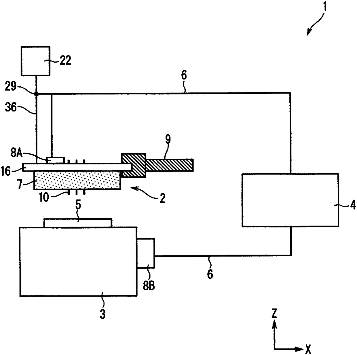
[0030] figure 1 It is a schematic side view showing the configuration of the evaluation device 1 according to Embodiment 1 of the present invention. figure 1 The evaluation device 1 is a device for evaluating electrical characteristics of an object to be measured. Hereinafter, the object to be measured will be described as a semiconductor device 5 such as a chip, but is not limited thereto, and may be, for example, a semiconductor wafer or the like. Before describing the evaluation device 1 , the semiconductor device 5 as the object to be measured will be described.
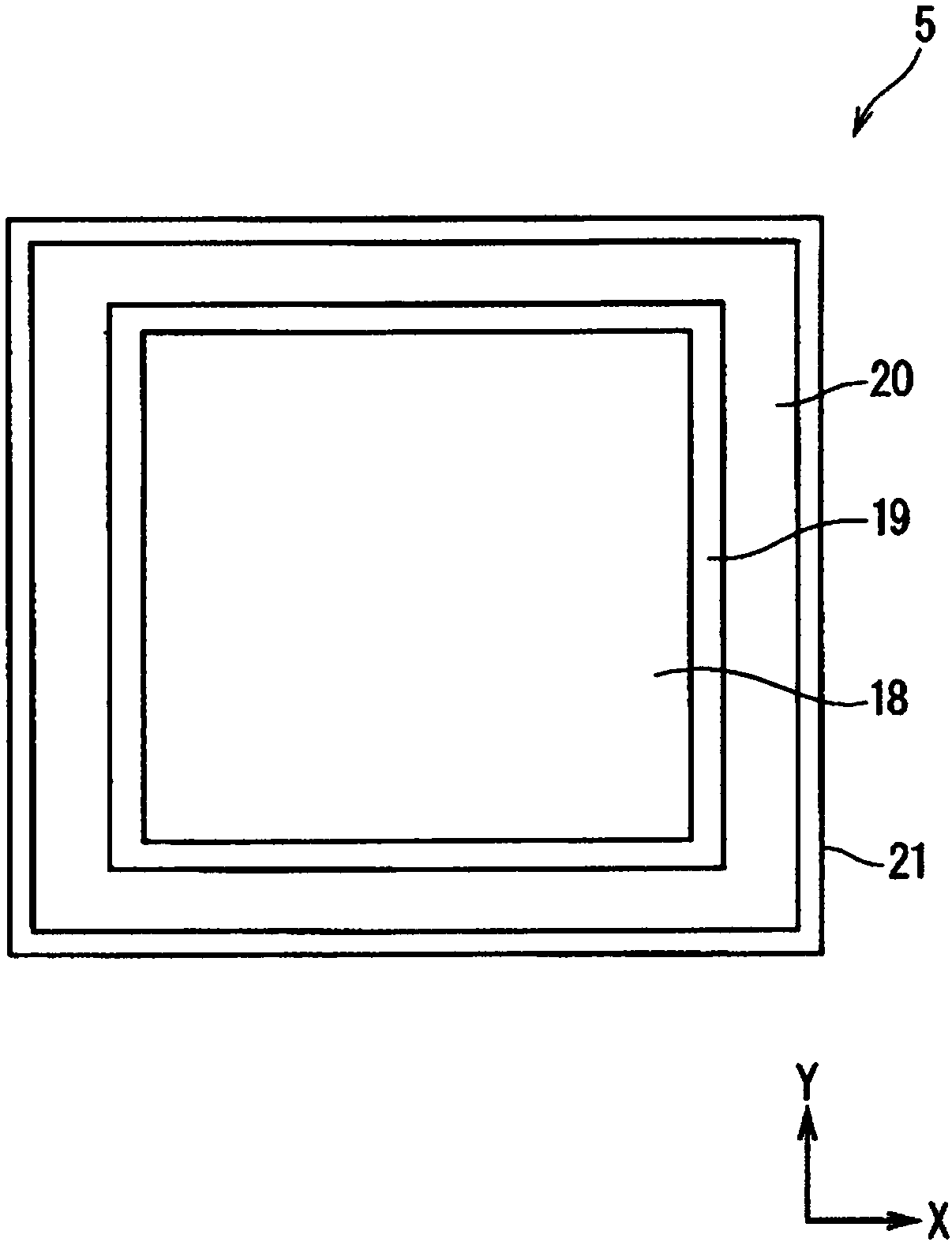
[0031] figure 2 It is a schematic plan view showing an example of the structure of the semiconductor device 5 . In Embodiment 1, the semiconductor device 5 is an IGBT (Insulated Gate Bipolar Transistor) with a vertical structure through which a large current flows vertically, that is, in the out-of-plane direction, but it is not limited thereto. The semiconductor device 5 has an active region 19 and a termin...
Embodiment approach 2
[0080] Figure 8 It is a schematic plan view showing a partial structure of an evaluation device 1 according to Embodiment 2 of the present invention, including a probe base 2 and a chuck table 3 . Hereinafter, among the constituent elements described in Embodiment 2, constituent elements that are the same as or similar to those in Embodiment 1 will be assigned the same reference numerals, and mainly different constituent elements will be described.
[0081] The evaluation device 1 according to the first embodiment described above ( Figure 4 ) includes a second gas supply unit 31 . In contrast, as Figure 8 As shown, the evaluation device 1 according to the second embodiment includes a third gas supply unit 32 instead of the second gas supply unit 31 .
[0082] The third gas supply unit 32 can supply gas toward the side wall portion 7 when the side wall portion 7 is close to the chuck table 3 . Thereby, the gas can be blown from the third gas supply part 32 to the side wa...
Deformed example 1
[0093] The evaluation device 1 described in each of Embodiment 1 and Embodiment 2 includes either one of the second gas supply unit 31 and the third gas supply unit 32 , but is not limited thereto. For example, as shown in Modification 1, the evaluation device 1 (not shown) may include both the second gas supply unit 31 and the third gas supply unit 32 . According to such a configuration, the effects of both Embodiments 1 and 2 can be obtained.
[0094] In addition, in Modification 1 and the like, at least any one of the first gas supply part 30 and the second gas supply part 31 may be arranged on the inner wall surface 34 of the side wall part 7 . exist Figure 9 (Schematic cross-sectional view) shows a structure in which four first gas supply parts 30 are respectively arranged on four inner wall surfaces 34 of the side wall part 7 ( Figure 8 ). According to such a structure, since the process of attaching the gas supply part to the mounting plate 16 is unnecessary, the s...
PUM
 Abstract
Description
Claims
Application Information
 - R&D
- Intellectual Property
- Life Sciences
- Materials
- Tech Scout
- Unparalleled Data Quality
- Higher Quality Content
- 60% Fewer Hallucinations
Browse by: Latest US Patents, China's latest patents, Technical Efficacy Thesaurus, Application Domain, Technology Topic, Popular Technical Reports.
© 2025 PatSnap. All rights reserved.Legal|Privacy policy|Modern Slavery Act Transparency Statement|Sitemap|About US| Contact US: help@patsnap.com