
Coiling device for warp knitted fabric

A coiling device and technology of warp knitted fabrics, which are applied in the directions of winding strips, transportation and packaging, and thin material processing, can solve problems such as poor use effect, mildew, damage, etc., to prevent mildew interference, increase service life, Easy-to-use effects

Inactive Publication Date: 2018-07-06
海宁市中发纺织有限公司
View PDF10 Cites 0 Cited by
  • Summary
  • Abstract
  • Description
  • Claims
  • Application Information

AI Technical Summary

Problems solved by technology

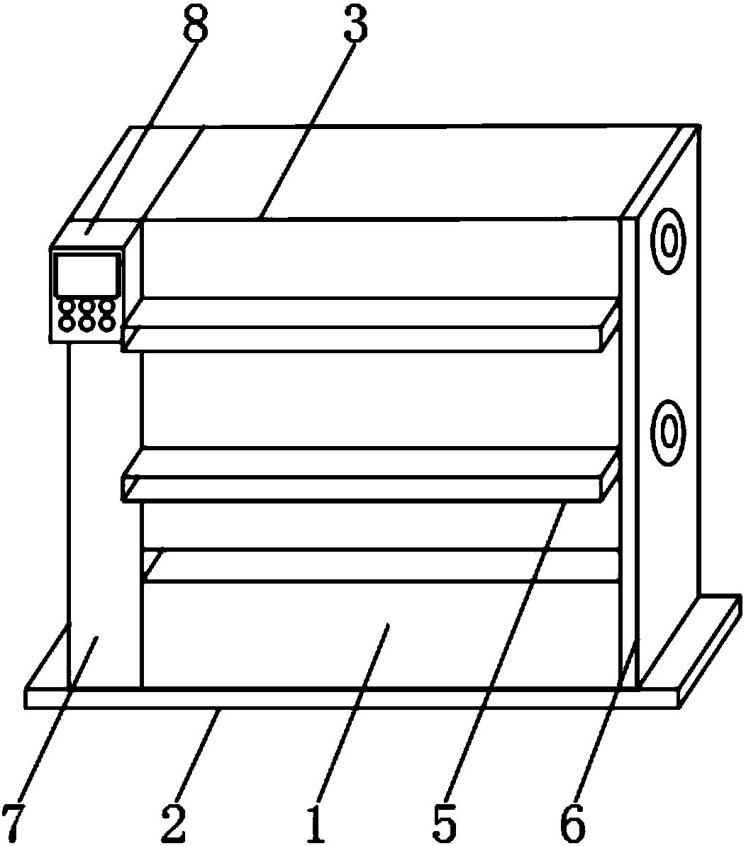
[0002] The take-up roller is a roller used to take up the sheet or film in the take-up device. The take-up mechanism actively and continuously drives the take-up roller by the worm gear, worm and sprocket to realize continuous take-up. The take-up roller mainly Used in the production and processing of warp-knitted fabrics, here we are talking about a warp-knitted fabric take-up device; the existing warp-knitted fabric take-up device has certain disadvantages in use, and it is impossible to combine the knitted fabric with external factors. If it is isolated, it is easily damaged by the influence of external water flow, etc., and the braided fabric cannot be guided and transported when it is taken, and the use effect is poor, and it is easy to be interfered by external humid gas during storage and become moldy, etc., resulting in its It cannot be used normally, which has a certain impact on the use of the warp knitted fabric take-up device. Therefore, we propose a warp knitted fabric take-up device

Method used

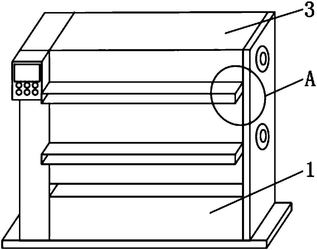
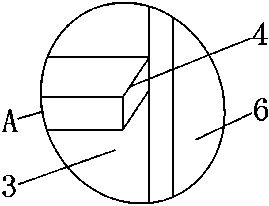

Image

  • Coiling device for warp knitted fabric
  • Coiling device for warp knitted fabric
  • Coiling device for warp knitted fabric

Examples


Embodiment Construction

[0018] In order to make the technical means, creative features, goals and effects achieved by the present invention easy to understand, the present invention will be further described below in conjunction with specific embodiments.

[0019] like Figure 1-5 As shown, a coiling device for warp knitted fabrics includes a drive box 1 and a moisture-proof splint 9, a load-bearing plate 2 is fixedly installed on the outer surface of the lower end of the drive box 1, and an isolation cover 3 is arranged above the drive box 1, and the isolation cover No. 1 material guide trough 4 is fixedly installed on the front end outer surface of 3 near the upper position, and No. 2 material guide trough 5 is fixedly installed on the front end outer surface of isolation cover 3 near the lower position, and the outer surface of one side of drive box 1 A fixed splint 6 is fixedly installed, and a control box 7 is fixedly installed on the outer surface of the other side of the drive box 1, and a con...


PUM


Abstract

The invention discloses a coiling device for warp knitted fabric. The coiling device comprises a driving box and a damp-proof clamping plate; a load-bearing plate is fixedly mounted on the outer surface of the lower end of the driving box, and an isolating outer cover is arranged above the driving box; a first material guiding groove is fixedly formed in the position, close to the upper portion, of the outer surface of the front end of the isolating outer cover; a second material guiding groove is fixedly formed in the position, close to the lower portion, of the outer surface of the front endof the isolating outer cover; and a fixing clamping plate is fixedly mounted on the outer surface of one side of the driving box, and a control box is fixedly mounted on the outer surface of the other side of the driving box. According to the coiling device for the warp knitted fabric, the isolating outer cover, the first material guiding groove and the damp-proof clamping plate are arranged, external interference can be isolated from the warp knitted fabric, guiding and conveying can be conducted on the warp knitted fabric, the interference of external moist gas on the kitted fabric can alsobe prevented, the coiling device is suitable for different working conditions, and better using prospects are brought.

Description

technical field [0001] The invention relates to the field of winding devices, in particular to a winding device for warp knitted fabrics. Background technique [0002] The take-up roller is a roller used to take up the sheet or film in the take-up device. The take-up mechanism actively and continuously drives the take-up roller by the worm gear, worm and sprocket to realize continuous take-up. The take-up roller mainly Used in the production and processing of warp-knitted fabrics, here we are talking about a warp-knitted fabric take-up device; the existing warp-knitted fabric take-up device has certain disadvantages in use, and it is impossible to combine the knitted fabric with external factors. If it is isolated, it is easily damaged by the influence of external water flow, etc., and the braided fabric cannot be guided and transported when it is taken, and the use effect is poor, and it is easy to be interfered by external humid gas during storage and become moldy, etc., r...

Claims


Application Information

Patent Timeline
IPC IPC(8): B65H18/08B65H20/04
CPCB65H18/08B65H20/04
Inventor 徐其金
Owner 海宁市中发纺织有限公司
Learn More