Eureka AIR delivers breakthrough ideas for toughest innovation challenges, trusted by R&D personnel around the world.

Circuit breaker automatic material separating table

A circuit breaker and automatic technology, applied in the direction of conveyor objects, transportation and packaging, etc., can solve the problem of difficult to achieve simple, neat and beautiful production scenes, difficult to achieve uninterrupted work mode, inconsistent supply speed and production speed, etc. problems, to achieve the effect of meeting quality requirements and stability, improving procedural and normative, and reducing labor costs

Inactive Publication Date: 2018-07-06
天津意献科技有限公司
View PDF0 Cites 1 Cited by
  • Summary
  • Abstract
  • Description
  • Claims
  • Application Information

AI Technical Summary

Problems solved by technology

When the material supply personnel perform the material supply work under the working state, it is difficult to achieve a concise, neat and beautiful production scene
The supply speed of raw materials in production is inconsistent with the production speed, which greatly affects the efficiency of production products
At the same time, because of the characteristics of manual operation, continuous work cannot be achieved, and it is difficult to achieve an uninterrupted working mode
Moreover, with the continuous increase of human resource costs, production costs will also increase, which is also harmful to this important link of production, and is not conducive to meeting the requirements of energy-saving production in enterprises

Method used


Image

  • Circuit breaker automatic material separating table

Examples


Embodiment Construction

[0015] In order to make the technical means, creative features, goals and effects achieved by the present invention easy to understand, the present invention will be further described below in conjunction with specific illustrations.

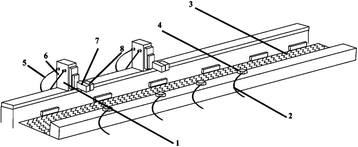
[0016] Such as figure 1 As shown, an automatic material partition table for a circuit breaker of the present invention includes a cylinder 1, a signal line 2, a conveyor belt 3, an infrared sensor 4, a control line 5, a power line 6, an elastic arm 7 and a buffer plate 8. The cylinder 1 is provided with a control line 5 and a power line 6, the infrared sensor 4 is provided with a signal line 2, the elastic arm 7 and the buffer sheet 8 are tightly connected together in the form of riveting, and the conveyor belt 3 is located in the middle of cylinder 1, control line 5, power line 6, elastic arm 7, buffer sheet 8, infrared sensor 4, and signal line 2, the cylinder 1, control line 5, power line 6, elastic arm 7, buffer sheet 8 is located on the le...


PUM


Abstract

The invention provides a circuit breaker automatic material separating table. The circuit breaker automatic material separating table comprises a cylinder, a signal line, a conveyor belt, an infraredsensor, a control line, a power line, an elastic arm and a buffer plate. The control line and the power line are arranged on the cylinder, the signal line is arranged on the infrared sensor, and the elastic arm and the buffer plate are tightly connected with each other in a riveting mode. The conveyer belt is positioned on the middle between the cylinder, the control line, the power line, the elastic arm, the buffer plate and the infrared sensor. The cylinder, the control line, the power line, the elastic arm, the buffer plate are arranged on the left side of the conveyer belt, and the infrared sensor and the signal line are arranged on the right side of the conveyer belt. The elastic arm and the buffer plate are arranged inside the cylinder and on the upper portion of the conveyer belt. By the power control of the cylinder, the effective monitoring of the infrared sensor and the organic coordination of the elastic arm and the buffer plate, it is guaranteed that the circuit breaker cancarry out the material separating operation on the conveyor belt accurately and orderly, the error in the work can be greatly reduced, the accuracy rate of products in the unit time can be improved,the manpower resource which should be manually operate is saved, and the cost of manpower cost is reduced.

Description

technical field [0001] The invention relates to the field of circuit breaker production equipment, in particular to an automatic material partition table for circuit breakers. Background technique [0002] With the development of today's society, the level of industrialization is getting higher and higher, and the technology is getting more and more advanced. The automation of the production line will gradually replace the manual production line. In the manual production mode, more labor costs are often consumed, and the number of products produced at the same time is far lower than the number of products produced under the automated production process. Due to the existence of individual differences in production personnel, the ability of each person is different, resulting in different feeding speeds in the process of feeding materials during production. When the material supply personnel perform the material supply work in the working state, it is difficult to achieve a c...

Claims


Application Information

Patent Timeline
Patent Type & Authority Applications(China)
IPC IPC(8): B65G47/29
CPCB65G47/29
Inventor 徐立刚
Owner 天津意献科技有限公司
Why Eureka
Eureka Blog
Learn More