
A resonant wireless power supply system and its power adjustment method and system

A power regulation system and wireless power supply technology, applied in circuit devices, electrical components, etc., can solve the problems of increased circuit cost, high cost, and IGBT heating of the whole machine.

Active Publication Date: 2021-05-14
ZONECHARGE (SHENZHEN) WIRELESS POWER TECH CO LTD
View PDF5 Cites 0 Cited by
  • Summary
  • Abstract
  • Description
  • Claims
  • Application Information

AI Technical Summary

Problems solved by technology

[0003] However, because the resonant loop of the LC parallel connection is uncontrollable, when the receiving end requires very little power, it can be reduced by reducing the pulse width of the driving PWM signal of the IGBT as the charging switch of the resonant ring (that is, the conduction time of the IGBT ) to reduce the transmission power of the transmitter, but if the driving PWM signal of the IGBT is too small, the IGBT will work in the unsaturated region and cause serious heating, which makes it difficult to accurately control the release of electromagnetic waves in the system, and the power cannot be adjusted from zero.
In order to solve the above problems, the power adjustment method in the prior art is to add a continuous adjustable switching power supply before the LC charging power supply, and adjust the output power by adjusting the voltage of the power supply during transmission. However, in a system with a large power, The cost of continuously adjustable switching power supply is relatively high, and the cost of the whole circuit is almost doubled

Method used


Image

  • A resonant wireless power supply system and its power adjustment method and system
  • A resonant wireless power supply system and its power adjustment method and system
  • A resonant wireless power supply system and its power adjustment method and system

Examples


Embodiment Construction

[0037] The core of the present invention is to provide a power adjustment method and system for a resonant wireless power supply system. On the one hand, the present invention can control the output power of the resonant ring to be adjusted from zero. On the other hand, it can obtain a more refined power adjustment effect. In addition, the cost of the method and device for obtaining the PWM signal is very low; another core of the present invention is to provide a resonant wireless power supply system including the power adjustment system of the resonant wireless power supply system.

[0038] In order to make the purpose, technical solutions and advantages of the embodiments of the present invention clearer, the technical solutions in the embodiments of the present invention will be clearly and completely described below in conjunction with the drawings in the embodiments of the present invention. Obviously, the described embodiments It is a part of embodiments of the present in...


PUM


Abstract

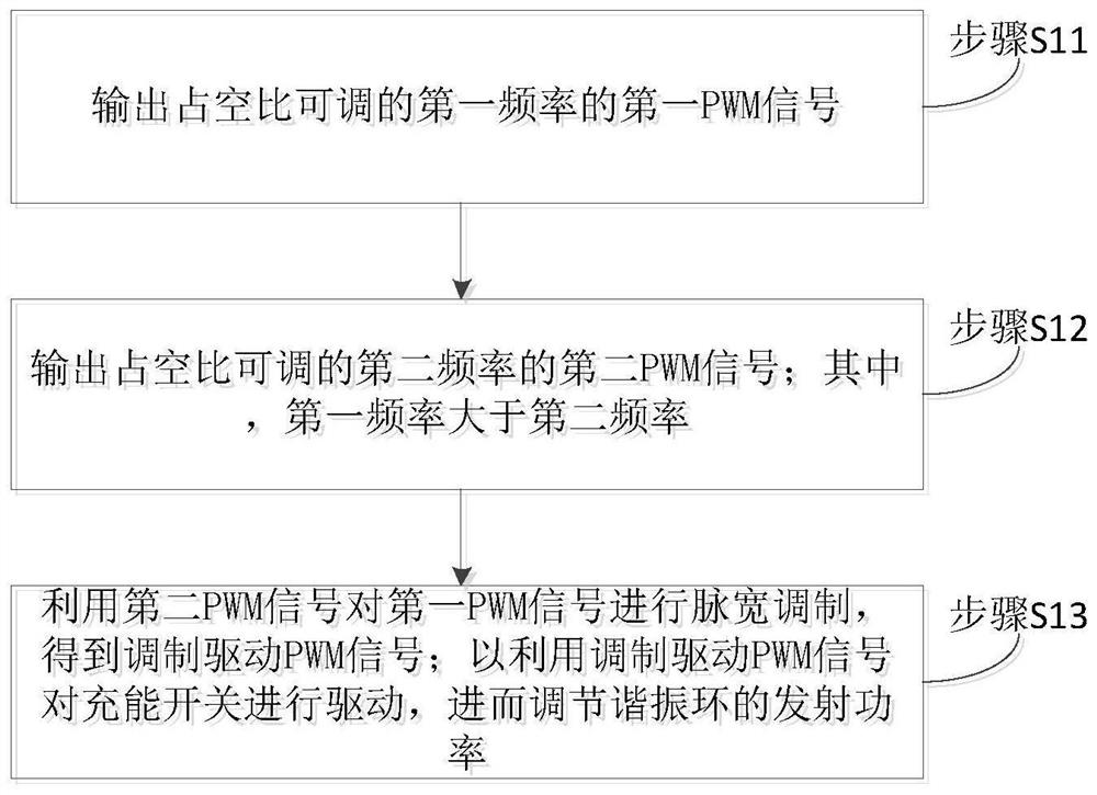
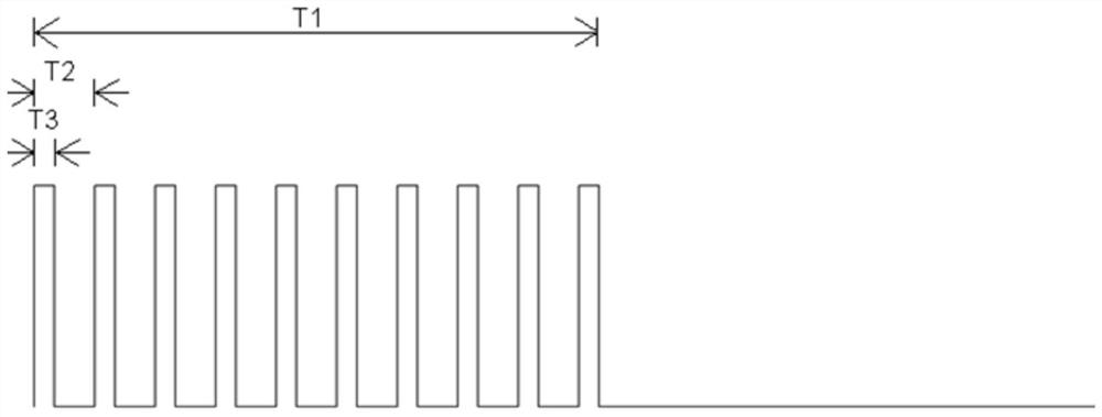
The invention discloses a resonant wireless power supply system and its power adjustment method and system. The resonant wireless power supply system includes a charging switch and a resonant ring connected to the charging switch. The method includes a first The first PWM signal of frequency; the second PWM signal of the second frequency with adjustable duty cycle; wherein, the first frequency is greater than the second frequency; the second PWM signal is used to perform pulse width modulation on the first PWM signal to obtain modulation Driving the PWM signal; the charging switch is driven by the modulated driving PWM signal, so as to adjust the transmission power of the resonant ring. On the one hand, the present invention can control the output power of the resonant ring to be adjusted from zero; on the other hand, it can obtain a finer power adjustment effect; in addition, the cost of the method and device for obtaining the PWM signal is very low.

Description

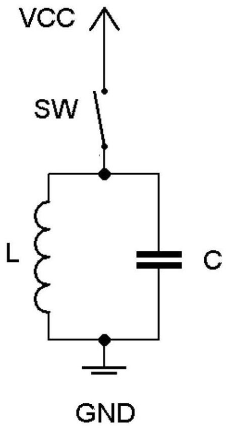
technical field [0001] The present invention relates to the technical field of wireless power supply, in particular to a resonant wireless power supply system and its power adjustment method and system. Background technique [0002] In the wireless power supply system, when the power of the load electrical appliances at the receiving end changes greatly, the transmitting end needs to continuously adjust the transmitting power. The resonant wireless power transmission system with LC parallel topology structure, because LC forms a loop, the electric energy will keep oscillating inside it when it is not charging, forming a process of continuously releasing electromagnetic waves. Compared with the LC series topology system, its advantages are sufficient resonance of the transceiver equipment, long transmission distance and high output power. [0003] However, because the resonant loop of the LC parallel connection is uncontrollable, when the receiving end requires very little p...

Claims


Application Information

Patent Timeline
Patent Type & Authority Patents(China)
IPC IPC(8): H02J50/12
Inventor 徐宝华蔡伟杰
Owner ZONECHARGE (SHENZHEN) WIRELESS POWER TECH CO LTD
Learn More