Convenient-to-use welding device

A welding device, a convenient technology, applied in the parts of the connection device, the device for preventing contact with live contacts, the coupling device, etc., can solve the problems of poor plug stability, user electric shock, poor contact, etc., and achieve convenient power connection Effects of connection and prevention of electric shock accidents

Inactive Publication Date: 2018-06-29
NINGBO ZHUXING MACHINERY DESIGN
View PDF0 Cites 0 Cited by
  • Summary
  • Abstract
  • Description
  • Claims
  • Application Information

AI Technical Summary

Problems solved by technology

[0002] With the popularity of metal or other thermoplastic materials, more and more welding machines are used. Welding is a manufacturing process that uses heat, high temperature, and high pressure to join metal or other thermoplastic materials. During the use of welding machines, it is necessary Electricity connection, the existing ones are usually plugged and unplugged directly through the plug to connect the electricity, but in the existing technology, the ordinary electric plug is prone to arc due to the influence of voltage during the plugging and unplugging process, and the generation of arc is likely to cause users There is a certain potential danger to the user, and there is poor plug stability, easy to loosen, resulting in poor contact, and because there is a large current flowing through the socket, the plug of the welding machine is easily damaged

Method used


Image

  • Convenient-to-use welding device
  • Convenient-to-use welding device
  • Convenient-to-use welding device

Examples


Embodiment Construction

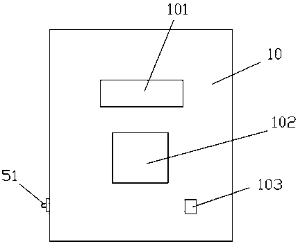
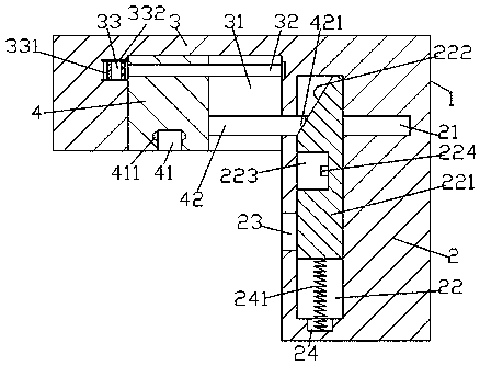
[0022] Such as Figure 1-Figure 6 As shown, a convenient welding device of the present invention includes a welding body 10 and a power connection device. The front end of the welding body 10 is respectively provided with a switch 103, a liquid crystal display 101, and a converter 102. The power connection The device includes a power connection box 1 and a power connection head 5 composed of a push-in part 3 and a power connection part 2. The push-in part 3 is fixedly arranged at the upper left side of the power connection part 2. The push-in part 3 A push-in sliding groove 31 is provided in the end surface of the bottom, and a first screw rod 32 extending left and right is arranged in the described push-in sliding groove 31, and the left side end of the first screw rod 32 is connected with the first motor 33 Connected, the right side end of the first screw rod 32 is rotationally connected with the right inner end of the push-in sliding groove 31, and the first screw rod 32 is...


PUM


Abstract

The invention discloses a convenient-to-use welding device. The device comprises a welding machine body and a power connection device; the front end surface of the welding machine body is provided with a switch, a liquid crystal display screen, and a converter; the power connection device comprises a power connection box and a power connection head, wherein the power connection box is composed ofa push-in portion and a power connection portion; the push-in portion is fixedly disposed at a position on the left side of the power connection portion; a push-in sliding groove is formed in the bottom end surface of the push-in portion; a first screw rod which extends leftwards and rightwards is arranged in the push-in sliding groove; the left end of the first screw rod is connected with a firstmotor; the right end of the first screw rod is in rotatable matched connection with the inner end of the right side of the push-in sliding groove; the first screw rod is provided with a clamping pushblock which is connected with the first screw rod in a threaded fit manner; and the end surface of the right side of the clamping push block below the first screw rod is provided with a push-in rod which extends rightwards. The convenient-to-use welding device of the invention is simple in structure. With the convenient-to-use welding device adopted, automatic power connection operation can be realized, the exposure and concealing operation of an electric pin can be automatically controlled, and work efficiency and safety can be improved.

Description

technical field [0001] The invention relates to the field of welding technology, in particular to a convenient and easy-to-use welding device. Background technique [0002] With the popularity of metal or other thermoplastic materials, more and more welding machines are used. Welding is a manufacturing process that uses heat, high temperature, and high pressure to join metal or other thermoplastic materials. During the use of welding machines, it is necessary Electricity connection, the existing ones are usually plugged and unplugged directly through the plug to connect the electricity, but in the existing technology, the ordinary electric plug is prone to arc due to the influence of voltage during the plugging and unplugging process, and the generation of arc is likely to cause users There is a certain potential danger to the user, and there is poor plug stability, easy to loosen, resulting in poor contact, and because there is a large current flowing through the socket, th...

Claims


Application Information

Patent Timeline
Patent Type & Authority Applications(China)
IPC IPC(8): H01R13/44H01R13/629H01R13/631H01R13/66
CPCH01R13/631H01R13/44H01R13/629H01R13/6675
Inventor 项侠风
Owner NINGBO ZHUXING MACHINERY DESIGN
Why Eureka
Try Eureka