
Simulation method and simulation system for antenna-shock tube-antenna plasma electromagnetic characteristics

A technology of plasma and electromagnetic characteristics, applied in the direction of design optimization/simulation, special data processing applications, etc., can solve the problems of short test duration, plasma refraction, simulation, etc., and achieve real simulation, cost-effective research, and cost reduction Effect

Active Publication Date: 2020-04-10
XIDIAN UNIV
View PDF5 Cites 0 Cited by
  • Summary
  • Abstract
  • Description
  • Claims
  • Application Information

AI Technical Summary

Problems solved by technology

It has a simple method of obtaining high-temperature airflow, a stable state, and a fairly clean hot airflow; as long as the initial conditions and the accurate measurement of the shock wave velocity are used, the rest of the flow parameters can be reliably obtained; the main disadvantage is the duration of the test. very short
[0004] At present, the shock tube is one of the mainstream devices in the study of the transmission characteristics of electromagnetic waves in plasma. The simulation of this process generally uses a one-dimensional transmission model. This model has the advantages of simplicity and speed. However, in the actual shock tube test Among them, the plasma flow field is non-uniform, and the electromagnetic wave will reflect on the wall of the shock tube, and there will be refraction and scattering in the plasma. The one-dimensional model cannot simulate these factors, and there is an urgent need for a more Simulation system close to the real situation

Method used


Image

  • Simulation method and simulation system for antenna-shock tube-antenna plasma electromagnetic characteristics
  • Simulation method and simulation system for antenna-shock tube-antenna plasma electromagnetic characteristics
  • Simulation method and simulation system for antenna-shock tube-antenna plasma electromagnetic characteristics

Examples


Embodiment Construction

[0046] The present invention will be further described in detail below in conjunction with the accompanying drawings and specific embodiments. It should be understood that the examples are only used to illustrate the present invention, but not to limit the protection scope of the present invention. In addition, it should be understood that after reading the content of the present invention, those skilled in the art may make various changes or modifications to the present invention, and these equivalent forms also fall within the scope of protection defined in the present application.

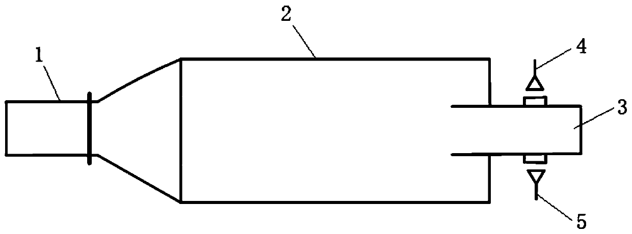
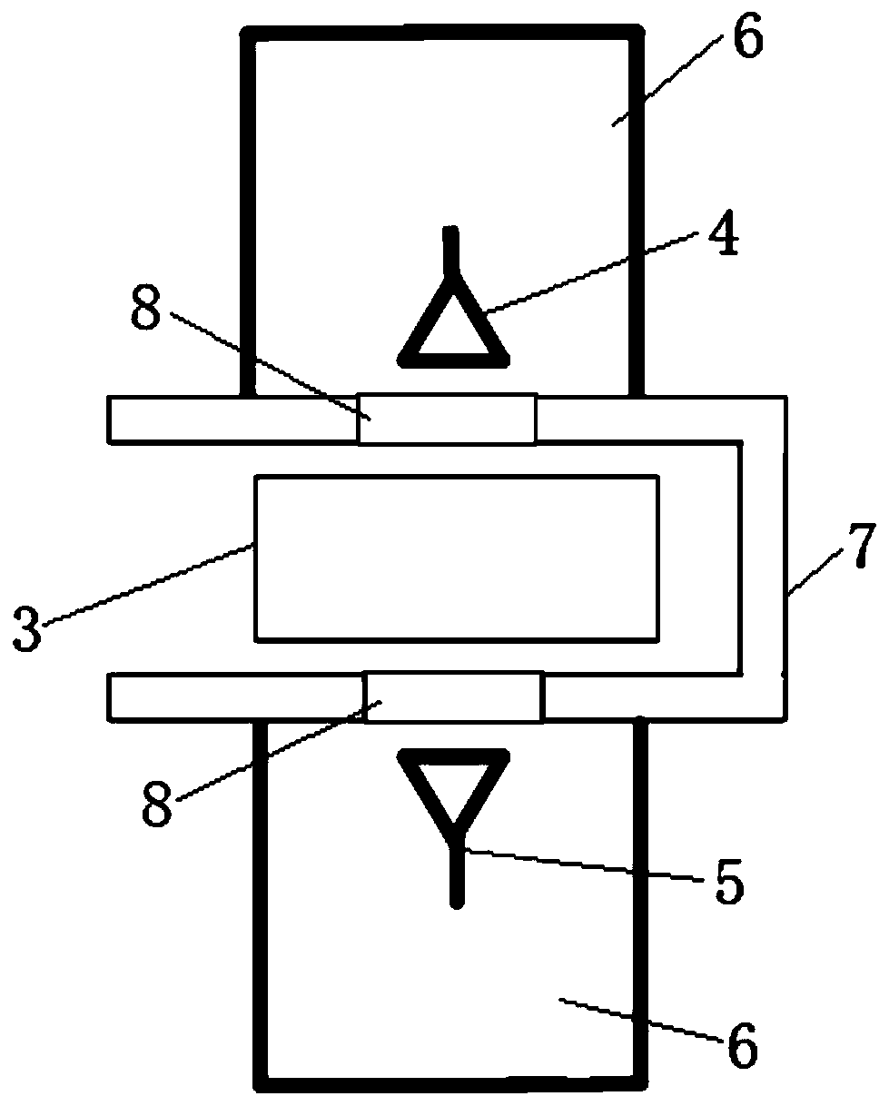
[0047] The basic idea of ​​the simulation method of the antenna-shock tube-antenna plasma electromagnetic characteristic simulation model of the present invention is: according to the structural shape, parameters and materials of the shock tube experimental device, combined with the shock tube experimental conditions to simulate the plasma in the shock tube The distribution of the flow field; at t...


PUM


Abstract

The invention discloses an antenna-shock tube-antenna plasma electromagnetic characteristic simulation method and system. The method comprises: determining dimensions of a shove tube experimental apparatus, electromagnetic parameters of a material used, structure, and experimental conditions; determining the size and structure of a simulation area; determining electromagnetic parameters of the material, and building a three-dimensional electromagnetic simulation model of the simulation area in a program; performing simulating according to the experimental conditions to obtain flow field distribution in a shock tube experimental segment; coupling simulation data of a flow field to meshes of the three-dimensional electromagnetic simulation model to obtain flow field data on the full-space electromagnetic meshes; coupling flow field mesh parameters to electromagnetic mesh parameters; filling the three-dimensional electromagnetic simulation model with the flow field electromagnetic parameters, and running the simulation program to obtain simulation results. A real simulation process is simulated via the program, flow field simulation and electromagnetic simulation are combined, and therefore, plasma interaction of electromagnetic wave with plasma in a shock tube is more truly simulated.

Description

technical field [0001] The invention belongs to the field of electromagnetic technology, and relates to a simulation method and simulation system for antenna-shock tube-antenna plasma electromagnetic characteristics, which are used to study the interaction between electromagnetic waves and plasma, and can be used to simulate the interaction between electromagnetic waves and plasma. The influence of uniform plasma on the transmission characteristics of electromagnetic waves, the experimental process of simulating the interaction between electromagnetic waves and plasma in shock tubes, etc. Background technique [0002] The shock tube is an important experimental research tool in many modern scientific and technological fields. It is widely used in gas physics, chemical dynamics, hypersonic gas dynamics, electromagnetic hydrodynamics and other fields. It is an important experimental device for experimentally studying the interaction between electromagnetic waves and plasma. ...

Claims


Application Information

Patent Timeline
Patent Type & Authority Patents(China)
IPC IPC(8): G06F30/20
CPCG06F30/20
Inventor 韩一平陈安涛艾夏吴哲锋孙浩宇崔志伟汪加洁赵文娟
Owner XIDIAN UNIV
Learn More