
DMA control device and image processor

A control unit, one-way technology, applied in the direction of electrical digital data processing, instruments, etc., can solve the problem of accurate and reasonable judgment of multiple requests of image function modules

Active Publication Date: 2018-06-29
ARKMICRO TECH
View PDF4 Cites 10 Cited by
  • Summary
  • Abstract
  • Description
  • Claims
  • Application Information

AI Technical Summary

Problems solved by technology

[0005] The purpose of the present invention is to provide a DMA control device and an image processor, aiming at solving the problem that the existing DMA control device cannot fully combine the image processing module to automatically perform DMA transmission parameters for the image data continuously input in real time in ISP processing The hardware configuration cannot combine image function modules to make accurate and reasonable decisions on multiple requests

Method used


Image

  • DMA control device and image processor
  • DMA control device and image processor
  • DMA control device and image processor

Examples


Embodiment 1

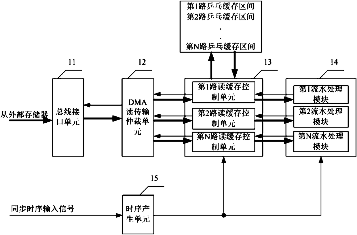
[0035] see figure 1 The DMA control device provided by Embodiment 1 of the present invention includes a bus interface unit 11, a DMA read transfer arbitration unit 12, an N-way read cache control unit 13, N pipeline processing modules 14, and a timing generation unit 15, wherein N is greater than or It is a natural number equal to 2, and the number of N depends on the number of pipeline processing modules in the image processor and the number of modules that need to access the external frame buffer.

[0036] The bus interface unit 11 is used to receive the read request signal and the transfer information generated by the DMA read transfer arbitration unit 12, and convert the read request signal and the transfer information into a bus request signal of a composite system bus protocol (such as an AXI bus, etc.). After receiving valid data on the bus, write the read buffer data read from the external memory to the DMA read transfer arbitration unit 12;

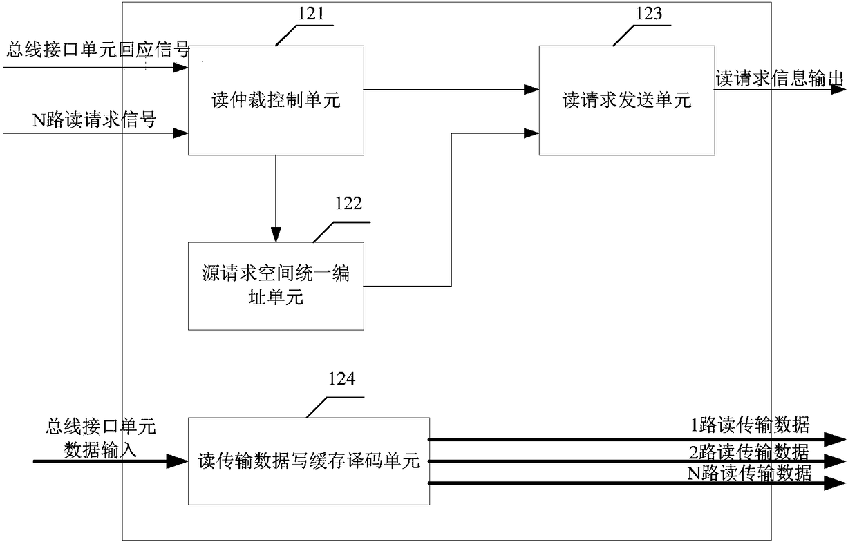
[0037] The DMA read tran...

Embodiment 2

[0063] see Figure 5 The difference between the DMA control device provided in Embodiment 2 of the present invention and the DMA control device provided in Embodiment 1 of the present invention is that the DMA control device provided in Embodiment 2 of the present invention further includes a DMA write transfer arbitration unit 22 and an N-way write buffer control Unit 23.

[0064] The bus interface unit is also used to receive the write request signal and the transfer information generated by the DMA write transfer arbitration unit 22, and convert the write request signal and the transfer information into a bus request signal of a composite system bus protocol (such as an AXI bus, etc.). After receiving a valid response on the bus, write the write buffer data read from the DMA write transfer arbitration unit 22 to the external memory;

[0065] The DMA write transfer arbitration unit 22 is used to be responsible for the arbitration of the DMA write request signal and to recei...


PUM


Abstract

The invention is applicable to the field of digital image processing, and provides a DMA control device and an image processor. The DMA control device comprises a bus interface unit, a DMA reading transmission arbitration unit, N paths of reading cache control units, a DMA writing transmission arbitration unit, N paths of writing cache control units, N pipeline processing modules and a time sequence generating unit, wherein N is a natural number larger than or equal to 2. In a chip system of real-time input like ISP, the DMA control device can conduct accurate and reasonable arbitration through the further utilization of an image processing module, and aiming at multiple paths of different data accessing requests, automatic hardware configuration of DMA transmission parameters can be achieved.

Description

technical field [0001] The invention belongs to the field of digital image processing, in particular to a DMA control device and an image processor. Background technique [0002] In the field of computer digital image processing technology, with the rapid development of semiconductor technology, the scale of SOC (System-On-a-Chip, System on Chip) chips is getting larger and larger, and the functions are becoming more and more complex, which requires continuous processing of large quantities of data. Handling and transport work. DMA (Direct Memory Access, direct memory access) technology is widely used in the transmission of large quantities of data in the system. After the DMA works, the data transfer does not require the CPU to participate, which reduces the burden on the CPU, so that the CPU can do it after starting the DMA. Other things, while greatly improving the efficiency of data transmission. [0003] In the existing DMA technology, usually according to some config...

Claims


Application Information

Patent Timeline
IPC IPC(8): G06F13/34
CPCG06F13/34
Inventor 袁扬智韦毅胡江鸣刘俊秀石岭
Owner ARKMICRO TECH
Learn More