Electric wire winding and cutting device
A technology of cutting device and wire coil, which is applied in the directions of transportation and packaging, transportation of filamentous materials, and processing of thin materials. The effect of low manufacturing cost
- Summary
- Abstract
- Description
- Claims
- Application Information
AI Technical Summary
Problems solved by technology
Method used
Image
Examples
Embodiment 1
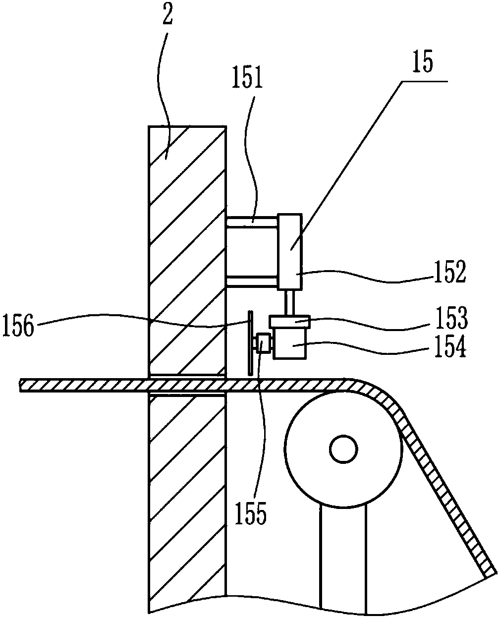
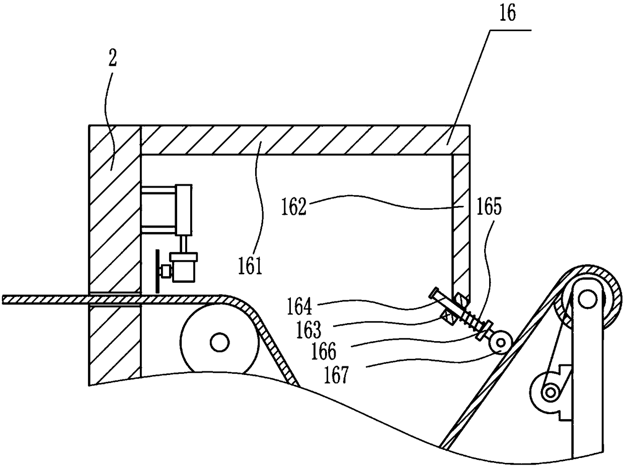
[0025] A wire coiling and cutting device, such as Figure 1-5 As shown, it includes a base 1, a first bracket 2, a first pole 4, a first roller 5, a second pole 6, a second roller 7, a second bracket 8, a first motor 9, and a first pulley 10. , the second pulley 11, the reel 12 and the belt 13 are fixedly connected with the first support 2 on the left side of the top of the base 1, have a through hole 3 on the first support 2, and are fixedly connected with the first support 2 on the base 1. A pole 4, the first pole 4 is positioned at the right side of the first support 2, the first roller 5 is connected to the rotation type on the first pole 4, the second pole 6 is fixedly connected on the base 1, the second Pole 6 is positioned at the right side of first pole 4, is fixedly connected with second support 8 on the top right side of base 1, is fixedly connected with first motor 9 on the left side of second support 8, on the first motor 9 A first pulley 10 is interference-connec...
Embodiment 2
[0027] A wire coiling and cutting device, such as Figure 1-5 As shown, it includes a base 1, a first bracket 2, a first pole 4, a first roller 5, a second pole 6, a second roller 7, a second bracket 8, a first motor 9, and a first pulley 10. , the second pulley 11, the reel 12 and the belt 13 are fixedly connected with the first support 2 on the left side of the top of the base 1, have a through hole 3 on the first support 2, and are fixedly connected with the first support 2 on the base 1. A pole 4, the first pole 4 is positioned at the right side of the first support 2, the first roller 5 is connected to the rotation type on the first pole 4, the second pole 6 is fixedly connected on the base 1, the second Pole 6 is positioned at the right side of first pole 4, is fixedly connected with second support 8 on the top right side of base 1, is fixedly connected with first motor 9 on the left side of second support 8, on the first motor 9 A first pulley 10 is interference-connec...
Embodiment 3
[0030] A wire coiling and cutting device, such as Figure 1-5 As shown, it includes a base 1, a first bracket 2, a first pole 4, a first roller 5, a second pole 6, a second roller 7, a second bracket 8, a first motor 9, and a first pulley 10. , the second pulley 11, the reel 12 and the belt 13 are fixedly connected with the first support 2 on the left side of the top of the base 1, have a through hole 3 on the first support 2, and are fixedly connected with the first support 2 on the base 1. A pole 4, the first pole 4 is positioned at the right side of the first support 2, the first roller 5 is connected to the rotation type on the first pole 4, the second pole 6 is fixedly connected on the base 1, the second Pole 6 is positioned at the right side of first pole 4, is fixedly connected with second support 8 on the top right side of base 1, is fixedly connected with first motor 9 on the left side of second support 8, on the first motor 9 A first pulley 10 is interference-connec...
PUM
 Abstract
Description
Claims
Application Information
 - Generate Ideas
- Intellectual Property
- Life Sciences
- Materials
- Tech Scout
- Unparalleled Data Quality
- Higher Quality Content
- 60% Fewer Hallucinations
Browse by: Latest US Patents, China's latest patents, Technical Efficacy Thesaurus, Application Domain, Technology Topic, Popular Technical Reports.
© 2025 PatSnap. All rights reserved.Legal|Privacy policy|Modern Slavery Act Transparency Statement|Sitemap|About US| Contact US: help@patsnap.com


