
An abutment system and method of use thereof

A base and substrate technology, applied in the directions of printing and printing devices, can solve the problems of poor adsorption force of the printing substrate, unfavorable high-precision printing, residual glue left on the printing base, etc., so as to improve the vacuum adsorption force and enhance the use range. , to improve the effect of fixed effects

Active Publication Date: 2019-10-29
BOE TECH GRP CO LTD
View PDF8 Cites 0 Cited by
  • Summary
  • Abstract
  • Description
  • Claims
  • Application Information

AI Technical Summary

Problems solved by technology

Among them, when the method of fixing with tape is used, it is easy to leave residual glue on the printing base, and when the printing height is low, it is easy to scratch the printing nozzle, which will cause damage to the equipment; when using vacuum adsorption to fix, due to the number of holes on the printing base Restrictions, when the area of ​​the printed substrate is small, such as the printing of the test substrate, the adsorption force of the printing base to the printed substrate is poor, and it is easy to move, rotate or slip, which is not conducive to high-precision printing

Method used


Image

  • An abutment system and method of use thereof
  • An abutment system and method of use thereof
  • An abutment system and method of use thereof

Examples


Embodiment Construction

[0049] In order to illustrate the present invention more clearly, the present invention will be further described below in conjunction with preferred embodiments and accompanying drawings. Similar parts in the figures are denoted by the same reference numerals. Those skilled in the art should understand that the content specifically described below is illustrative rather than restrictive, and should not limit the protection scope of the present invention.

[0050]Various structural schematic diagrams according to embodiments of the present disclosure are shown in the accompanying drawings. The figures are not drawn to scale, with certain details exaggerated and possibly omitted for clarity of presentation. The shapes of various regions and layers shown in the figure, as well as their relative sizes and positional relationships are only exemplary, and may deviate due to manufacturing tolerances or technical limitations in practice, and those skilled in the art may Regions / lay...


PUM


Abstract

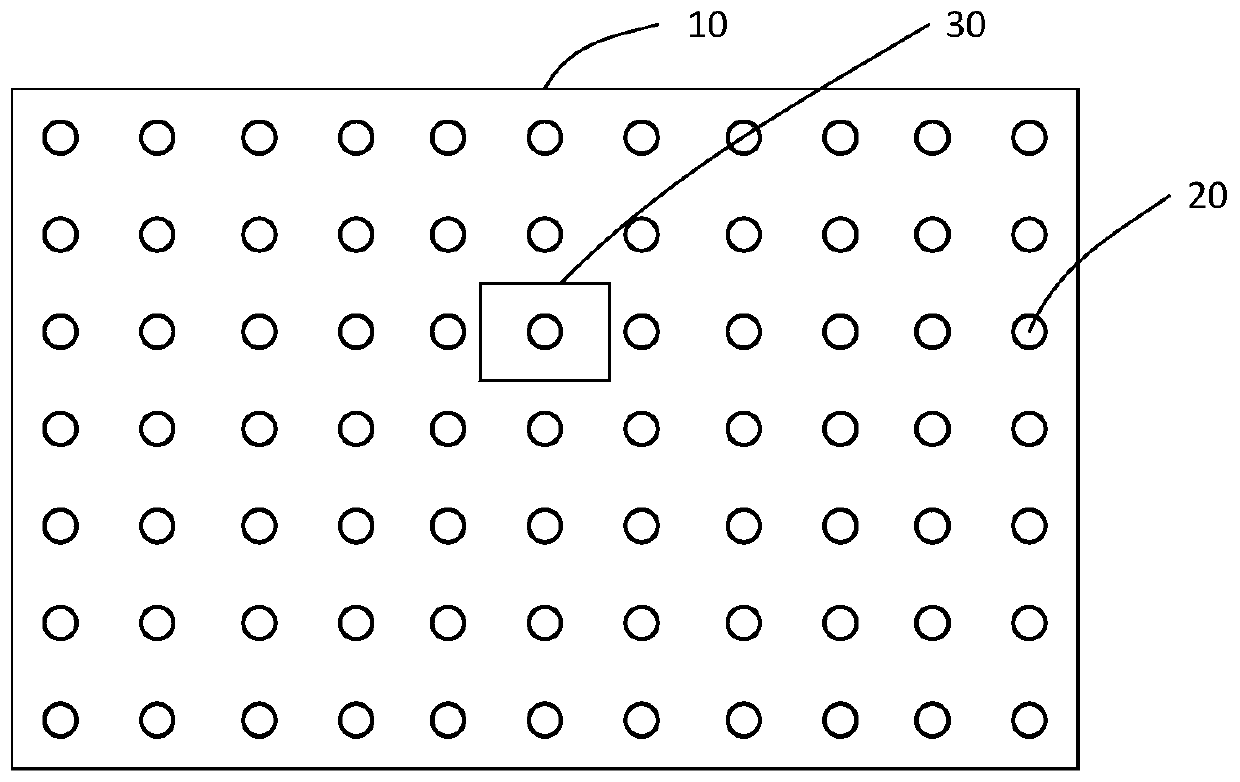
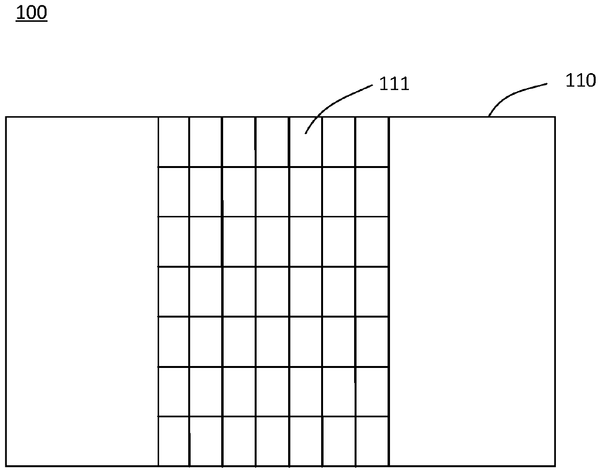
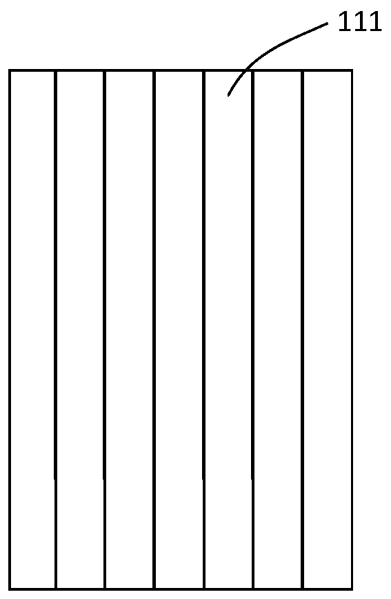
The invention discloses a printing base station. The printing base station comprises a base station body and a plurality of ventilating components provided with ventilating holes, wherein a printing base plate is arranged on the surface of the base station body, the surface of the base station body at least comprises a hollowed-out portion, and the hollowed-out portion is composed of a lattice structure; and the multiple ventilating components are arranged in the lattice structure movably, so that the density of the corresponding ventilating holes below the printing base plate is regulated, and the printing base plate is adsorbed in a vacuum mode. The invention further discloses a printing method applied to the printing base station. By changing the positions of the ventilating componentson the surface of the base station body, accordingly, the density of the through holes of a printing area is changed, the vacuum adsorption capability of the small-size printing base plate is improved, and the fixing effect on the printing base plate is improved.

Description

technical field [0001] The invention relates to the technical field of adsorption and fixing devices. More specifically, it relates to a printing platform and a printing method thereof. Background technique [0002] Organic electroluminescent devices such as OLEDs have the characteristics of ultra-thinness, all solid state, high luminous brightness and efficiency, excellent color saturation, wide viewing angle, fast response, and wide application temperature range (-40°C to 70°C). It has become the first choice for high-end mobile phones, TVs, watches and other electronic equipment, and has broad application prospects in the field of display technology. At present, the equipment and technology for making OLED products by inkjet printing method are becoming more and more mature. Specifically, the materials used to make OLED display substrates can be dissolved in inkjet printing solvents to form inkjet printing inks. The nozzle sprays inkjet printing ink onto the glass subst...

Claims


Application Information

Patent Timeline
Patent Type & Authority Patents(China)
IPC IPC(8): B41J29/08
CPCB41J29/08
Inventor 张渊明王熙元
Owner BOE TECH GRP CO LTD
Learn More