Direct driving device of self-bearing motor

A driving device and bearing motor technology, applied in the direction of electromechanical devices, electric components, electrical components, etc., can solve the problems of large mechanical friction torque, complex control system, difficult transportation, etc., to eliminate friction torque, high transmission efficiency, maintenance low cost effect

Inactive Publication Date: 2018-06-26
NANJING INST OF ASTRONOMICAL OPTICS & TECH NAT ASTRONOMICAL OBSE
View PDF5 Cites 4 Cited by
  • Summary
  • Abstract
  • Description
  • Claims
  • Application Information

AI Technical Summary

Problems solved by technology

[0002] At present, the rotary table is generally supported by hydrostatic bearings and mechanical bearings. Since the structural design of hydrostatic bearings is very complicated, the manufacturing precision is very high, and a set of hydraulic devices is required (a complete hydraulic system is powered by a power components, actuators, control components, auxiliary components and hydraulic oil), which leads to hydrostatic bearings requiring professionals to maintain
In addition, there are still disadvantages such as large vibration and noise, large space occupation, high maintenance costs, and difficult transportation.
Moreover, the rotary working turntable supported by mechanical bearings has the disadvantages of large mechanical friction torque, severe nonlinearity, large power consumption, complex control system, and low control accuracy.

Method used


Image

  • Direct driving device of self-bearing motor
  • Direct driving device of self-bearing motor
  • Direct driving device of self-bearing motor

Examples


Embodiment 1

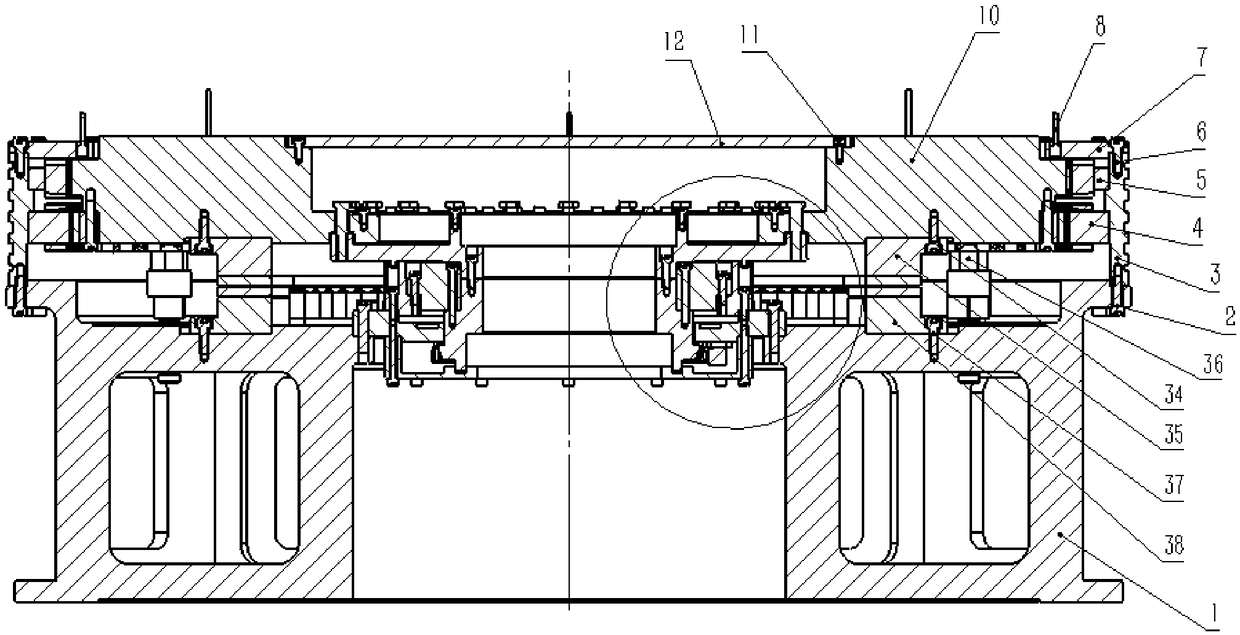
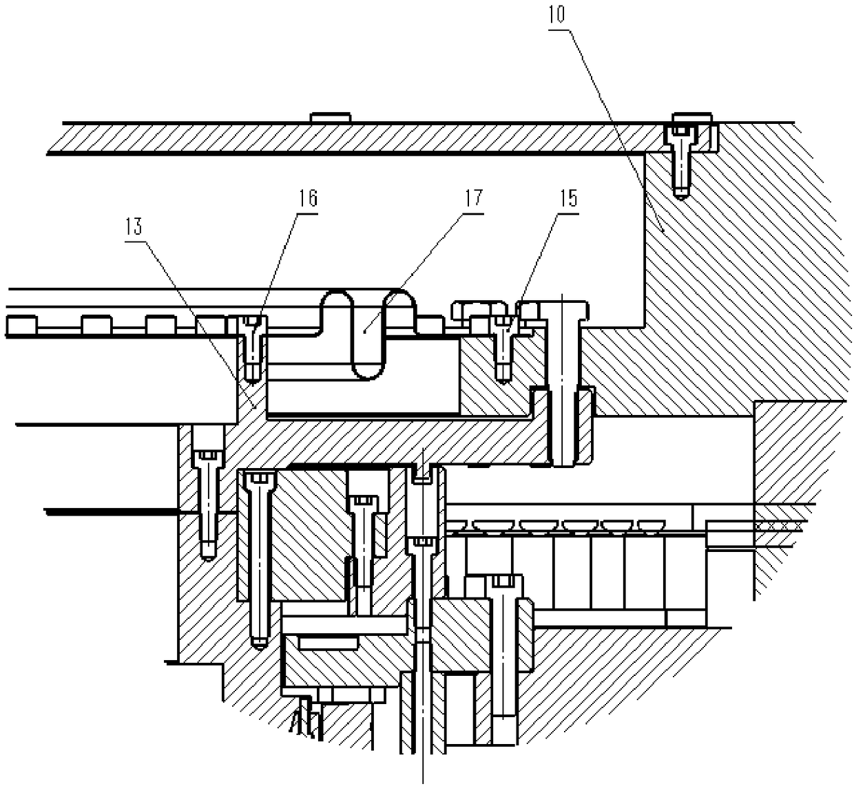
[0048] Embodiment 1, self-bearing motor direct drive device, such as figure 1 , figure 2 As shown, the self-bearing direct drive device of the present invention is mainly composed of a base 1, a direct drive motor 4, a radial active magnetic suspension bearing 5, a radial active magnetic suspension bearing position sensor 9, a rotary table 10, an axial protection bearing 36, Axial active offset magnetic suspension bearing unit upper 35, axial active offset magnetic suspension bearing unit lower 37, axial active offset magnetic suspension bearing position sensor 8, axial active offset magnetic suspension bearing unit 40, flexible connection parts 17. Mandrel adapter plate 13, mandrel 19, radial protection bearing 21, bearing seat 26, angular displacement sensor 27, reading head 30, sealing end cover 31, and mandrel protection end cover 12. The self-bearing direct drive device is placed horizontally, and the load is installed on the rotary table 10. Initialization is carried ...


PUM


Abstract

A direct driving device of a self-bearing motor is provided with a central rotation body, a magnetic suspension bearing and a direct driving motor, wherein the central rotation body is in rotation symmetry, the magnetic suspension bearing is used for restraining the rotation body to do axial and radial movement, the direct driving motor drives the central rotation body, the central rotation body in rotation symmetry forms a rotation workbench, a load is arranged on the rotation workbench, the magnetic suspension bearing for restraining the rotation body to do axial and radial movement comprises an upper axial permanent-magnet bias magnetic suspension bearing, a lower axial permanent-magnet bias magnetic suspension bearing, four axial bias magnetic suspension bearing or bearing units and four axial active magnetic suspension or bearing units, each bearing or bearing unit forms the magnetic suspension bearing system of the device, and moreover, an axial / radial rolling bearing is arrangedand used as a protection bearing. The direct driving device is easy to process and assemble and has the advantages of no friction, low power consumption, high transmission efficiency, high rotation positioning accuracy, and no climbing phenomenon during rotation at an ultralow speed.

Description

technical field [0001] The invention relates to a rotary device directly driven by a self-bearing motor, in particular to a self-bearing motor direct drive device for a rotary table. The present invention is the research achievement of the following projects: National Natural Science Foundation General Project (Project No.: 11573046, 11273039), Chinese Academy of Sciences Astronomy Special Project (C-113). Background technique [0002] At present, the rotary table is generally supported by hydrostatic bearings and mechanical bearings. Since the structural design of hydrostatic bearings is very complicated, the manufacturing precision is very high, and a set of hydraulic devices is required (a complete hydraulic system is powered by a power Components, executive components, control components, auxiliary components and hydraulic oil), which leads to hydrostatic bearings requiring professionals to maintain. In addition, there are disadvantages such as large vibration and noise...

Claims


Application Information

Patent Timeline
Patent Type & Authority Applications(China)
IPC IPC(8): H02K7/09H02K7/10H02K11/22
CPCH02K7/09H02K7/10H02K11/22
Inventor 任长志张夏杰乐中宇徐进叶宇
Owner NANJING INST OF ASTRONOMICAL OPTICS & TECH NAT ASTRONOMICAL OBSE
Why Eureka
Try Eureka