
Electrical connector

An electrical connector and contact pin technology, which is applied in the direction of connection, two-part connection device, circuit, etc., can solve the problems of small contact area between the pins of the shielding sheet and the shielding shell, unstable, and affecting the shielding effect of the electrical connector, etc. Achieve better shielding effect and stable grounding effect

Active Publication Date: 2018-06-26
FOXCONN (KUNSHAN) COMPUTER CONNECTOR CO LTD +1
View PDF5 Cites 3 Cited by
  • Summary
  • Abstract
  • Description
  • Claims
  • Application Information

AI Technical Summary

Problems solved by technology

However, due to the small and unstable contact area between the pins of the shielding piece and the shielding shell, it will affect the shielding effect of the entire electrical connector.

Method used


Image

  • Electrical connector
  • Electrical connector
  • Electrical connector

Examples


Embodiment Construction

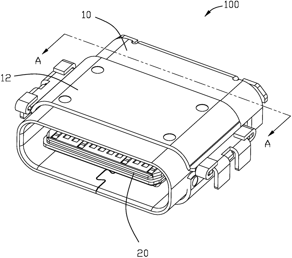
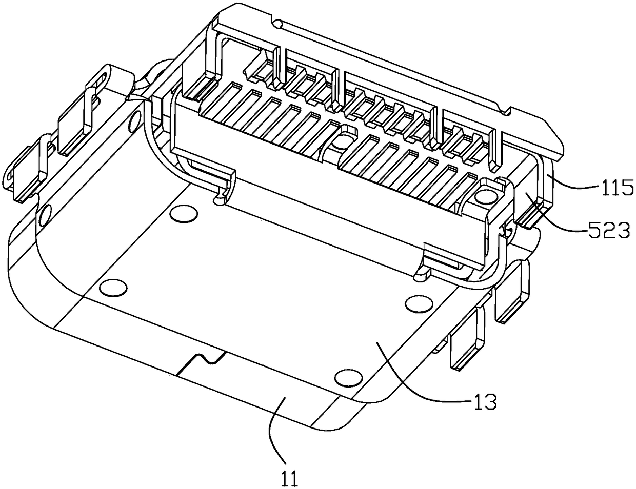
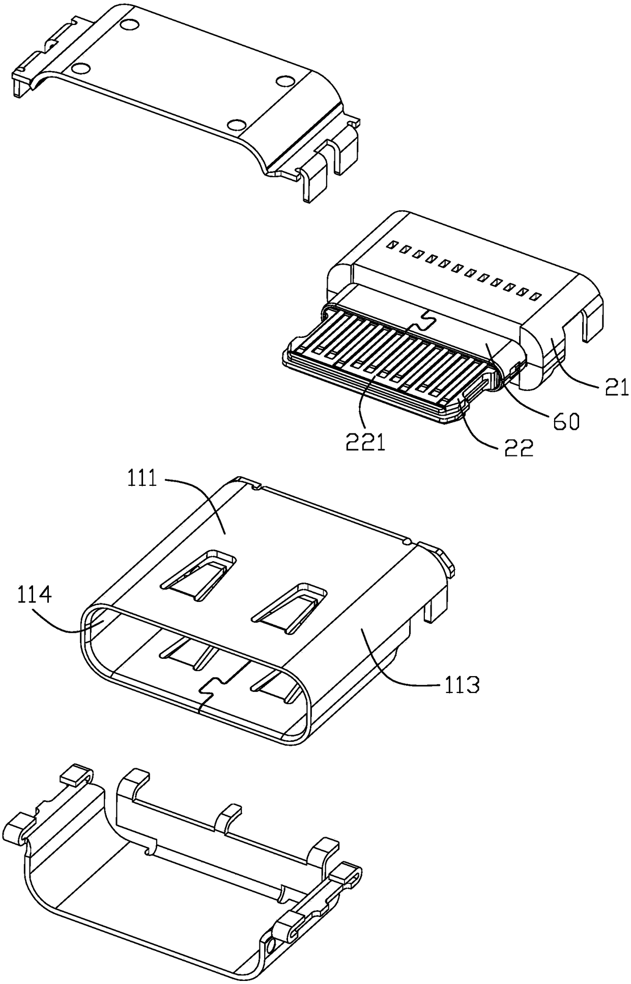
[0042] Below, will combine Figure 1 to Figure 7 The electric connector of the present invention is introduced in detail.

[0043] Please refer to Figure 1 to Figure 4 As shown, the electrical connector 100 of the present invention is mounted on a circuit board (not shown), and the electrical connector 100 includes a terminal module 20 and a shielding shell 10 surrounding the terminal module 20 . The terminal module 20 includes an insulating body 30 and a conductive terminal 40 fixed on the insulating body 30 . The terminal module 20 includes a base 21 and a mating tongue 22 extending forward from the base 21 . A step is further provided at the root of the mating tongue 22 , and the electrical connector 100 further includes a grounding member 60 surrounding the step. The ground member 60 extends at least with an abutting portion 61 , and the abutting portion 61 is fixed on the base 21 and contacts with the shielding case 10 .

[0044] The shielding housing 10 includes an ...


PUM


Abstract

The invention relates to an electrical connector. The electrical connector includes a terminal module set and a covering shell surrounding the terminal module set; the terminal module set includes aninsulation body, upper-row conductive terminals, lower-row conductive terminals, and a shielding sheet, wherein the upper-row conductive terminals and the lower-row conductive terminals are held in the insulation body, and the shielding sheet is located between the upper-row conductive terminals and the lower-row conductive terminals; the upper-row conductive terminals and the lower-row conductiveterminals are provided with contact portions and connection pins; the rear end of the insulation body is provided with a mounting surface; the connection pins of the upper-row conductive terminals and the lower-row conductive terminals are arranged on the mounting surface; the shielding sheet extends to the mounting surface; the shielding sheet is provided with a lap joint portion exposed on themounting surface; contact pins extend out of the rear end of the covering housing; and the contact pins extend to the mounting surface and contact with the shielding sheet. According to the electricalconnector of the present invention, the contact pins extending out of the covering housing contact with the shielding sheet, so that the overall shielding effect of the electrical connector is better.

Description

【Technical field】 [0001] The invention relates to an electric connector with more stable and better shielding effect. 【Background technique】 [0002] China Utility Model Announcement No. 204216260 patent discloses an electrical connector, which includes a shielding shell, an insulating body, a plurality of upper row conductive terminals and a plurality of lower row conductive terminals, and a grounding piece located on the insulating body. Pins extend downward from the rear of the grounding sheet, and the pins are in contact with the inner wall of the shielding shell. However, since the contact area between the pins of the shield sheet and the shield shell is small and very unstable, the shielding effect of the entire electrical connector will be affected. [0003] Therefore, it is necessary to provide a new electrical connector to solve the above problems. 【Content of invention】 [0004] The purpose of the present invention is to provide an electrical connector with bet...

Claims


Application Information

Patent Timeline
Patent Type & Authority Applications(China)
IPC IPC(8): H01R13/6581H01R13/516
CPCH01R13/516H01R13/6581H01R12/725H01R13/6595H01R24/60H01R13/6585H01R13/506H01R13/6594
Inventor 赵俊
Owner FOXCONN (KUNSHAN) COMPUTER CONNECTOR CO LTD
Learn More