
Rolling stock axle interference assembly contact stress analysis method based on simulation

A contact stress and analysis method technology, applied in computer-aided design, special data processing applications, instruments, etc., can solve the problems that the quality of the wheel set cannot be accurately predicted and measured, the analysis is limited, and the problem cannot be described.

Inactive Publication Date: 2018-06-22
谢红太
View PDF1 Cites 5 Cited by
  • Summary
  • Abstract
  • Description
  • Claims
  • Application Information

AI Technical Summary

Problems solved by technology

At present, a lot of research has been done on the press-fitting process of wheel axle technology based on tribological principles and finite element analysis theory in China, but there are relatively few studies on the surface contact stress of the hub hole of the wheel seat after the press-fitting of the wheel set. Strain gauges and stress analysis devices cannot be pasted on the two internal contact surfaces. It is difficult to track and measure the pressure state of the currently widely used cold and hot loading methods. The quality of the assembled wheelset cannot be accurately predicted and actually measured. Only It can be determined based on long-term practical experience, and the safety and reliability are low
In the traditional interference assembly stress calculation, it is often assumed that the contact stress on both sides is evenly distributed along the axis direction, and the analysis model is simplified and summarized as an ideal axisymmetric two-dimensional plane stress problem. The analysis has relatively large limitations, and the problem cannot be accurately and effectively described.

Method used


Image

  • Rolling stock axle interference assembly contact stress analysis method based on simulation
  • Rolling stock axle interference assembly contact stress analysis method based on simulation
  • Rolling stock axle interference assembly contact stress analysis method based on simulation

Examples


Embodiment Construction

[0025] Taking the research on contact stress of CRH2 type EMU trailer wheel pair axle interference assembly as an example, the present invention will be further described with reference to the accompanying drawings.

[0026] Such as figure 1 Shown is a working flow chart of the present invention based on the simulation method for analyzing the contact stress of the railway locomotive vehicle axle interference assembly contact stress. The detailed steps are as follows:

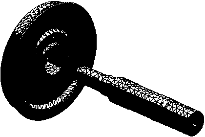
[0027] Step 1: The three-dimensional model of wheel and axle interference transfer, using SolidWorks to establish three-dimensional digital models of the wheels and axles of railway locomotives, and complete their virtual assembly. At the same time, the model is simplified, simplified to a wheel and half axle mode, and some small rounded corners and small chamfers are omitted, such as figure 2 shown;

[0028] Step 2: Transfer the finite element model of the wheel shaft interference fit, transfer the 3D mode...


PUM


Abstract

The invention provides a rolling stock axle interference assembly contact stress analysis method based on simulation. The method includes taking a CRH2-type high-speed train trailer wheels as prototypes, and creating a three-dimensional digital model for axle interference assembly by SolidWorks software; converting the three-dimensional digital model for axle interference assembly into a SolidWorks finite element analysis module simulation, and creating a finite element model; setting the contacting mode of a contact surface group of wheel set-wheel axle interference assembly to be shrink fit,and performing interference contact stress analysis; selecting a plurality of different axle interference values within a specific range in an equal difference mode to perform analysis. The rolling stock axle interference assembly contact stress analysis method has the advantages that yield strength limits of axle materials are compared on the basis of multiple finite element analysis data, reasonableness and reliability of the interference range are judged and illustrated, and an interference-stress function model for axle interference assembly is determined.

Description

technical field [0001] The invention relates to a finite element analysis method of a mechanical structure in the field of rail transportation, in particular to a method for analyzing a contact stress of a railway locomotive vehicle wheel shaft interference assembly based on Simulation. Background technique [0002] The railway locomotive bogie is one of the most critical components of the high-speed EMU train, which is located between the running rail and the underframe of the car body. As an important deformed part connecting the bogie and the ground rail, the wheelset transmits the all-directional load from the impact of the line and the vibration of the vehicle itself, which directly affects the running quality and safety of the train. In order to adapt to the high-speed, comfortable and safe high-quality EMU passenger cars, my country adopts the LMA type wheel tread with excellent dynamic performance and large operating stability to match the T60 rail in the three-dimen...

Claims


Application Information

Patent Timeline
IPC IPC(8): G06F17/50
CPCG06F30/15G06F30/23G06F2119/06
Inventor 谢红太谢斌斌
Owner 谢红太
Learn More