
Special lifting device for rectangular steel plate

A technology of rectangular steel plates and spreaders, applied in the direction of load hanging elements, transportation and packaging, etc.

Pending Publication Date: 2018-06-19
王文娇
View PDF4 Cites 0 Cited by
  • Summary
  • Abstract
  • Description
  • Claims
  • Application Information

AI Technical Summary

Problems solved by technology

[0003] Currently, there is no such device on the market

Method used


Image

  • Special lifting device for rectangular steel plate
  • Special lifting device for rectangular steel plate
  • Special lifting device for rectangular steel plate

Examples


Embodiment Construction

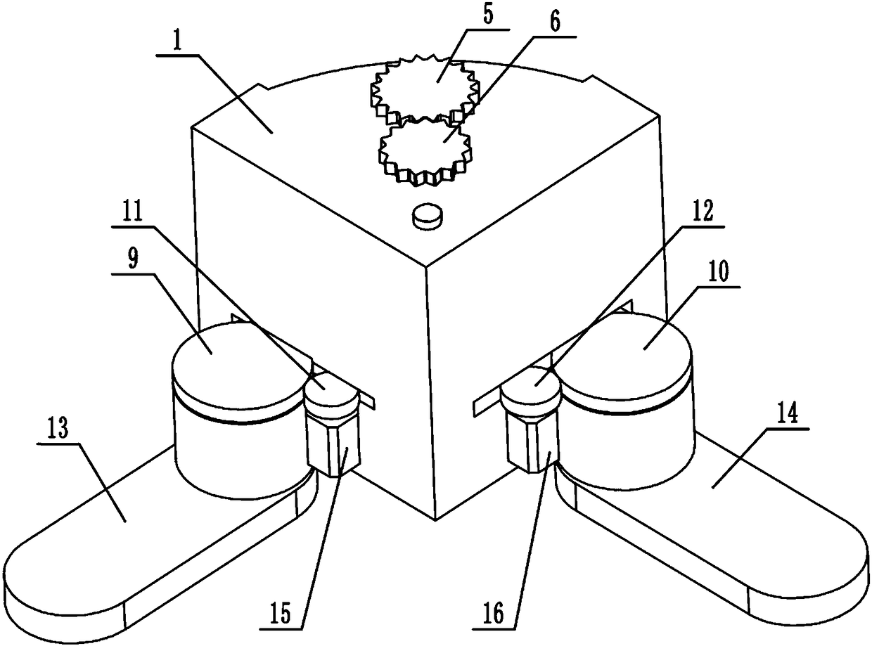
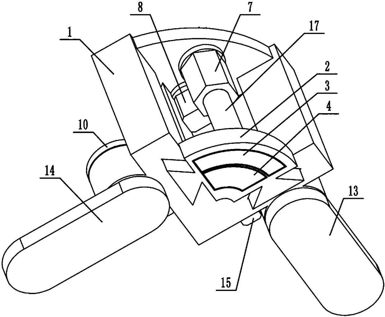
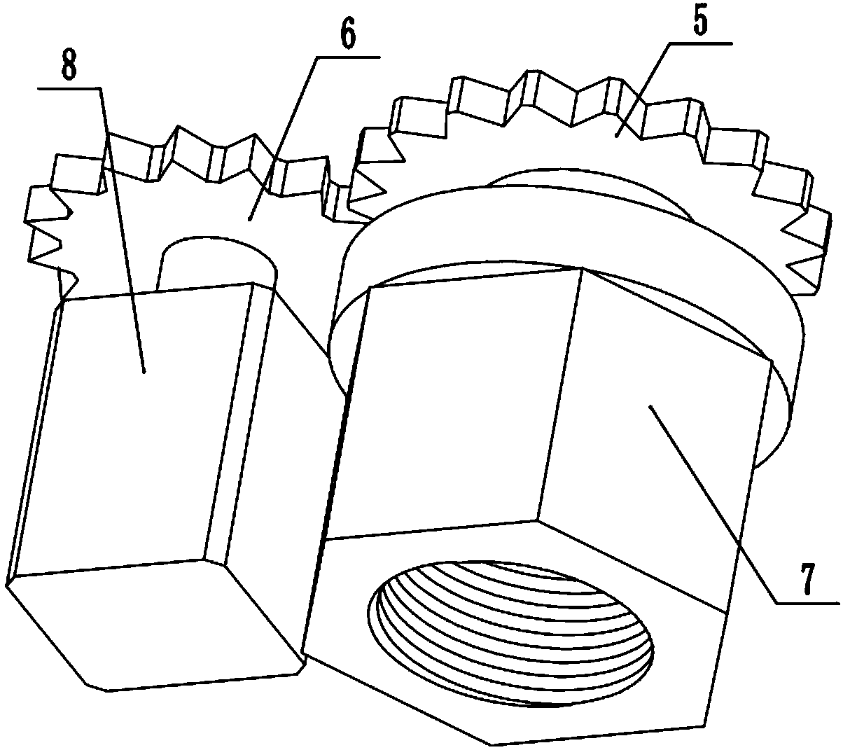
[0018] A special hanger for rectangular steel plates is composed of a frame 1, a pressure plate 2, a first electromagnet 3, a second electromagnet 4, a first driven gear 5, a first driving gear 6, a first lead screw slider 7, First motor 8, first driven round wheel 9, second driven round wheel 10, first driving round wheel 11, second driving round wheel 12, first supporting plate 13, second supporting plate 14, second motor 15. The third motor 16, the first lead screw 17, the first housing 18, the second housing 19, the third housing 20 and the suspension ring 21, the frame 1 structurally includes the main frame 101, the first installation Hole 102, Second Mounting Hole 103, First Dovetail Groove 104, Second Dovetail Groove 105, Third Mounting Hole 106, Fourth Mounting Hole 107, Rack Upper Surface 108, Ring Lug 109, Rack Inner Facade 110 , the first circular wheel groove 111, the second circular wheel groove 112, the first outer surface 113 of the frame and the second outer su...


PUM


Abstract

The invention relates to a special lifting device for a rectangular steel plate, belongs to the field of lifting tools, and concretely relates to the device, which adopts electromagnets for attractingand a fixture for clamping four corners of the steel plate so as to lift the steel plate conveniently. By using multiple devices at the same time, the safety is greatly improved, and the working efficiency is improved; during a lifting process, the steel plate does not directly contact a steel wire rope, so that the steel wire rope is prevented from being worn and broken, the service life of thesteel wire rope is prolonged, and a potential safety hazard is eliminated; during the lifting process, the lifting device has a certain locking force on the steel plate, so that the steel plate is noteasy to slide, and the lifting process is stable and safe; and the special lifting device for the rectangular steel plate provided by the invention is compact in overall structure, convenient to operate, safe and fast, and beneficial to reducing the working intensity of workers, and ensuring the personal safety of the workers.

Description

technical field [0001] The invention relates to a special hoisting tool for rectangular steel plates, specifically a device which uses electromagnets to absorb and clamps the edge of the steel plate to facilitate hoisting, and belongs to the field of hoisting tools. Background technique [0002] Generally, industrial and mining enterprises directly use wire ropes to lift thicker steel plates. The traditional lifting method is to pass more than two wire ropes through the lower surface of the steel plate, and then hang the ends of the wire ropes on the crane hook for lifting. During the lifting process, the steel wire rope wears at the edges and corners of the steel plate edge, which is prone to broken strands and shortens the service life of the steel wire rope. Moreover, because the force direction of the force point of the steel wire rope on the edge of the steel plate is different from the lifting direction, the resulting force makes the steel wire rope move towards the m...

Claims


Application Information

Patent Timeline
Patent Type & Authority Applications(China)
IPC IPC(8): B66C1/06
CPCB66C1/06
Inventor 王文娇高壮壮由子浩
Owner 王文娇
Learn More