Electric plug-in devices and electric plug-in equipment for new energy vehicles
An electric device and electric power technology, which is applied to the components of the connection device, coupling device, connection, etc., can solve the problems of detachment of the charging head and the charging interface, poor connection stability, and unstable contact, so as to increase safety and prevent short circuits , The effect of preventing charging interruption
- Summary
- Abstract
- Description
- Claims
- Application Information
AI Technical Summary
Problems solved by technology
Method used
Image
Examples
Embodiment 1
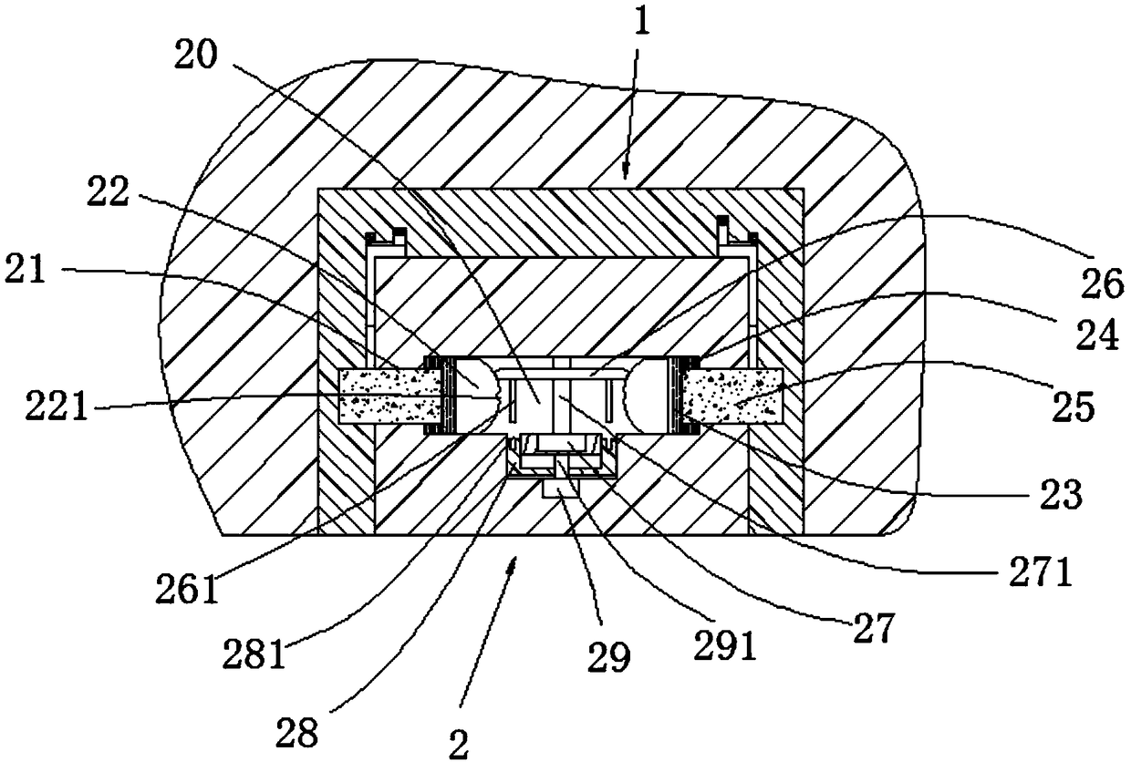
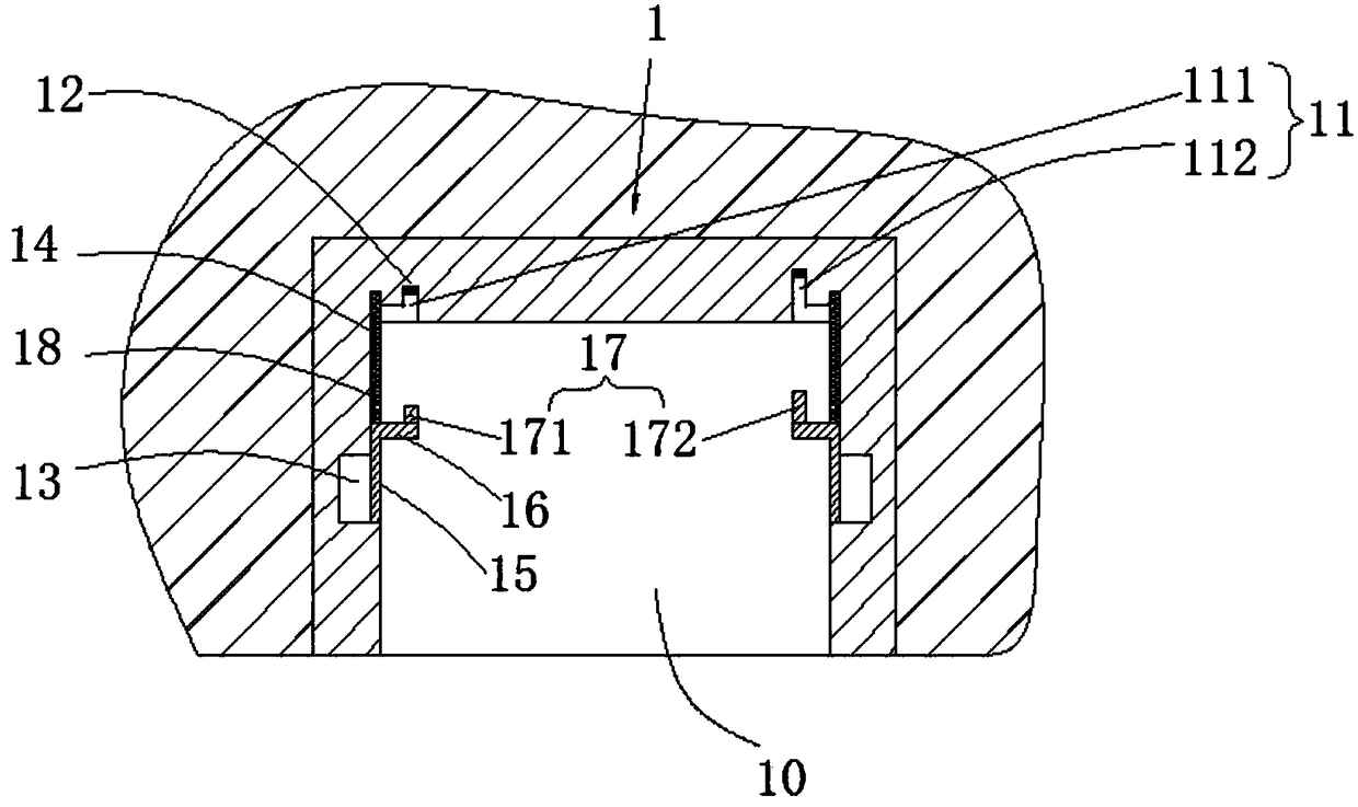
[0024]This embodiment provides an electric power connection and plugging device, which includes a power connection base 1 and a power connection head 2. The power connection base 1 includes an insertion slot 10 with an opening facing the front end. A counterbore 11 is provided at the bottom of the insertion slot 10. The counterbore 11 is provided with a sensor 12, and the left and right side walls of the insertion groove 10 are symmetrically provided with a power connection groove 13, and the rear end of the power connection groove 13 is also provided with a longitudinal sliding groove 14, and in the longitudinal sliding groove 14 A sealing plate 15 is slidably installed, and the rear end of the sealing plate 15 is fixedly provided with a push rod 16. There is a trigger part 17 matched with the counterbore 11, a longitudinal elastic member 18 is arranged in the longitudinal sliding groove 14, and the front end of the longitudinal elastic member 18 is in contact with the rear en...
Embodiment 2
[0026] This embodiment provides an electric power connection and plugging device, which includes a power connection base 1 and a power connection head 2. The power connection base 1 includes an insertion slot 10 with an opening facing the front end. A counterbore 11 is provided at the bottom of the insertion slot 10. The counterbore 11 is provided with a sensor 12, the counterbore 11 includes a first counterbore 111 and a second counterbore 112, the sensor 12 in the first counterbore 111 is an instant sensor, and controls the first motor 27 work, the sensor 12 in the second counterbore 112 is a time-delay sensor, controls the second motor 29 to work, and the left and right side walls of the insertion slot 10 are symmetrically provided with the electric connection groove 13, and the electric connection groove 13 The rear end is also provided with a longitudinal sliding groove 14, and a sealing plate 15 is slidably installed in the longitudinal sliding groove 14. The rear end of ...
Embodiment 3
[0028] This embodiment provides an electric power connection and plugging device, which includes a power connection base 1 and a power connection head 2. The power connection base 1 includes an insertion slot 10 with an opening facing the front end. A counterbore 11 is provided at the bottom of the insertion slot 10. The counterbore 11 includes a first counterbore 111 and a second counterbore 112, and the first counterbore 111 is shallower than the second counterbore 112, the counterbore 11 is provided with a sensor 12, and the insertion groove 10 The left and right side walls are symmetrically provided with power connection grooves 13, and the rear end of the power connection groove 13 is also provided with a longitudinal sliding groove 14, and a sealing plate 15 is slidably installed in the longitudinal sliding groove 14, and the rear end of the sealing plate 15 is fixed. A push rod 16 is provided, the end of the push rod 16 away from the sealing plate 15 extends into the ins...
PUM
 Abstract
Description
Claims
Application Information
 - R&D
- Intellectual Property
- Life Sciences
- Materials
- Tech Scout
- Unparalleled Data Quality
- Higher Quality Content
- 60% Fewer Hallucinations
Browse by: Latest US Patents, China's latest patents, Technical Efficacy Thesaurus, Application Domain, Technology Topic, Popular Technical Reports.
© 2025 PatSnap. All rights reserved.Legal|Privacy policy|Modern Slavery Act Transparency Statement|Sitemap|About US| Contact US: help@patsnap.com


