
Non-heated rotary dehydration equipment

A dehydration equipment and rotary technology, applied in lighting and heating equipment, drying solid materials without heating, centrifuges, etc., can solve the problems of unsuitable materials heated by heating equipment, difficulty in quick operation, increased construction and manufacturing costs, etc. , to achieve the effect of saving construction cost, improving performance and saving energy

Active Publication Date: 2019-11-05
思威博(北京)生物科技有限公司
View PDF14 Cites 0 Cited by
  • Summary
  • Abstract
  • Description
  • Claims
  • Application Information

AI Technical Summary

Problems solved by technology

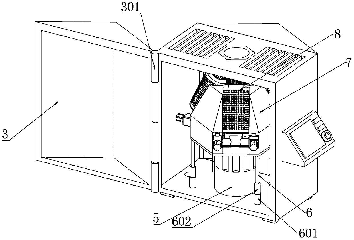
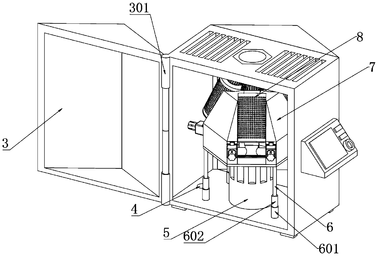
[0008] In order to solve the above-mentioned technical problems, the present invention provides non-heating rotary dehydration equipment to solve the existing dehydration equipment. During dehydration, there are many transmission power units, and the energy and power utilization is relatively slack, resulting in energy waste and construction and manufacturing costs. In addition, the existing dehydration equipment often requires additional drying and heating equipment for drying, and the heating equipment is not suitable for materials that are not suitable for heating. Due to the multi-stage separation treatment, it is difficult to quickly start the operation The problem

Method used


Image

  • Non-heated rotary dehydration equipment
  • Non-heated rotary dehydration equipment
  • Non-heated rotary dehydration equipment

Examples


Embodiment

[0034] as attached figure 1 to attach Figure 9 Shown:

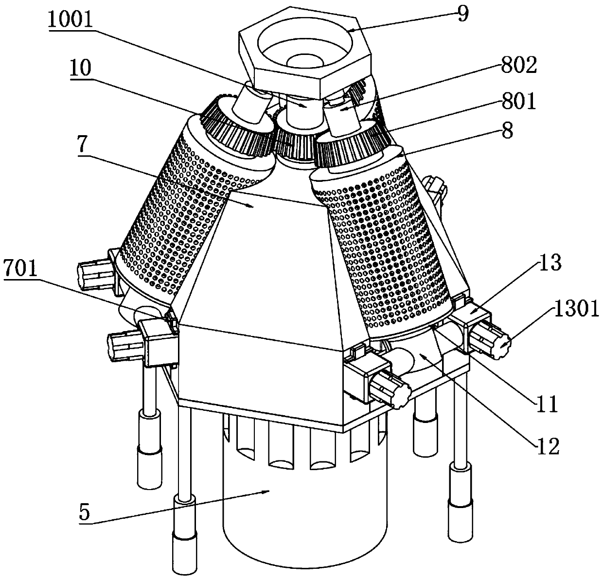
[0035] The invention provides a non-heating rotary dehydration device, which includes a body 1, a control panel 2, a chamber door 3, a drain port 4, a servo motor 5, a supporting positioning column 6, a dehydration shell 7, a dehydration cylinder 8, a fixed plate 9, Main gear plate 10, bottom head 11, T-shaped body 12, fixed block 13, middle support plate 14, rotating shaft 15, ventilation hole 101, hinge 301, fixed sleeve 601, movable pin 602, positioning body 701, barrel groove 702 , fixed hole 703, driven gear plate 801, driven connecting column 802, driving bearing collar 901, driven bearing collar 902, driving connecting column 1001, storage tank 1101, solid column 1102, fixing bolt 1301, flat plate Paddle 1501, level paddle 1502 and limit block 70101, the control panel 2 is fixed on the left end side wall of the body 1, and the body 1 is a regular hexahedron structure; seven groups of ventilation holes 101 are le...


PUM


Abstract

The invention provides non-heating rotary dewatering equipment. The non-heating rotary dewatering equipment comprises an equipment body, a hierarchical paddle and a limiting block, wherein a control panel is fixed to the side wall of the left end of the equipment body, and the equipment body is of a regular hexahedron structure; seven sets of ventilation holes are reserved in a plane at the top ofthe equipment body; a cavity door is rotatably connected to the front end of the equipment body through a vertical hinge at the left side. A driving gear and driven gears are arranged, the driving gear is of a truncated cone structure which is narrow at top and wide at bottom, the driven gears are aslant wound around the driving gear for 60 degrees separately, the driving gear and the driven gears are meshed with one another, thus it is achieved that the driving gear is driven by anticlockwise rotation of a servo motor to drive the drive gears to rotate clockwise, the construction cost of a transmission mechanism is saved, the rotary utilization rate of the servo motor is increased, compared with traditional dewatering equipment, the mode of adopting multiple transmission motors is adopted, energy is better saved, and the high cost for motor maintenance is saved.

Description

technical field [0001] The invention belongs to the technical field of material dehydration equipment, and more specifically relates to non-heating rotary dehydration equipment. Background technique [0002] The main part of the dehydration equipment is the inner tank, and there are small holes around the inner tank, and the clothes to be dehydrated are placed in the inner tank. The motor drives the inner tank to rotate at high speed through the belt to generate a large centrifugal force, so the water is thrown out through the small holes on the inner tank, and is collected and discharged uniformly. Generally speaking, for wet materials, the dehydration equipment works for two minutes. The drying effect is almost the same as that achieved by the dryer working for 20 minutes, but the dehydration equipment cannot completely dry the material. Therefore, a way to save time and energy is to dehydrate wet clothes first, and then dry them after dehydration. [0003] And as a kind...

Claims


Application Information

Patent Timeline
Patent Type & Authority Patents(China)
IPC IPC(8): B04B5/10F26B5/08F26B21/00
CPCB04B5/10F26B5/08F26B21/001
Inventor 朱柏艳朱世新
Owner 思威博(北京)生物科技有限公司
Learn More