
Rotary locking mechanism and its applied vehicle lock and locking control method

A technology of rotary locking and control method, applied in the field of car lock and locking control, and rotary locking mechanism, can solve the problems of large site dependence, hidden danger of safety performance, easy to be damaged, etc., to achieve compact and effective control process, parts Simple structure and wide range of effects

Active Publication Date: 2019-11-29
GUANGDONG LOFANDI INTELLIGENT TECH CO LTD
View PDF5 Cites 0 Cited by
  • Summary
  • Abstract
  • Description
  • Claims
  • Application Information

AI Technical Summary

Problems solved by technology

[0003] This type of external locking structure is simple, requires a large number of external locking products, poor portability, high cost, and the locking reliability is not strong, it is easy to be damaged, and there are great hidden dangers in safety performance. It is more dependent on the venue, especially the shared bicycles that appear now. The purpose of this model is to share and rent public bicycle resources anytime and anywhere. This kind of public bicycles basically cannot be rented at fixed points. To use the lock that comes with the car to realize the locking and unlocking of the bicycle

Method used


Image

  • Rotary locking mechanism and its applied vehicle lock and locking control method
  • Rotary locking mechanism and its applied vehicle lock and locking control method
  • Rotary locking mechanism and its applied vehicle lock and locking control method

Examples


Embodiment 1

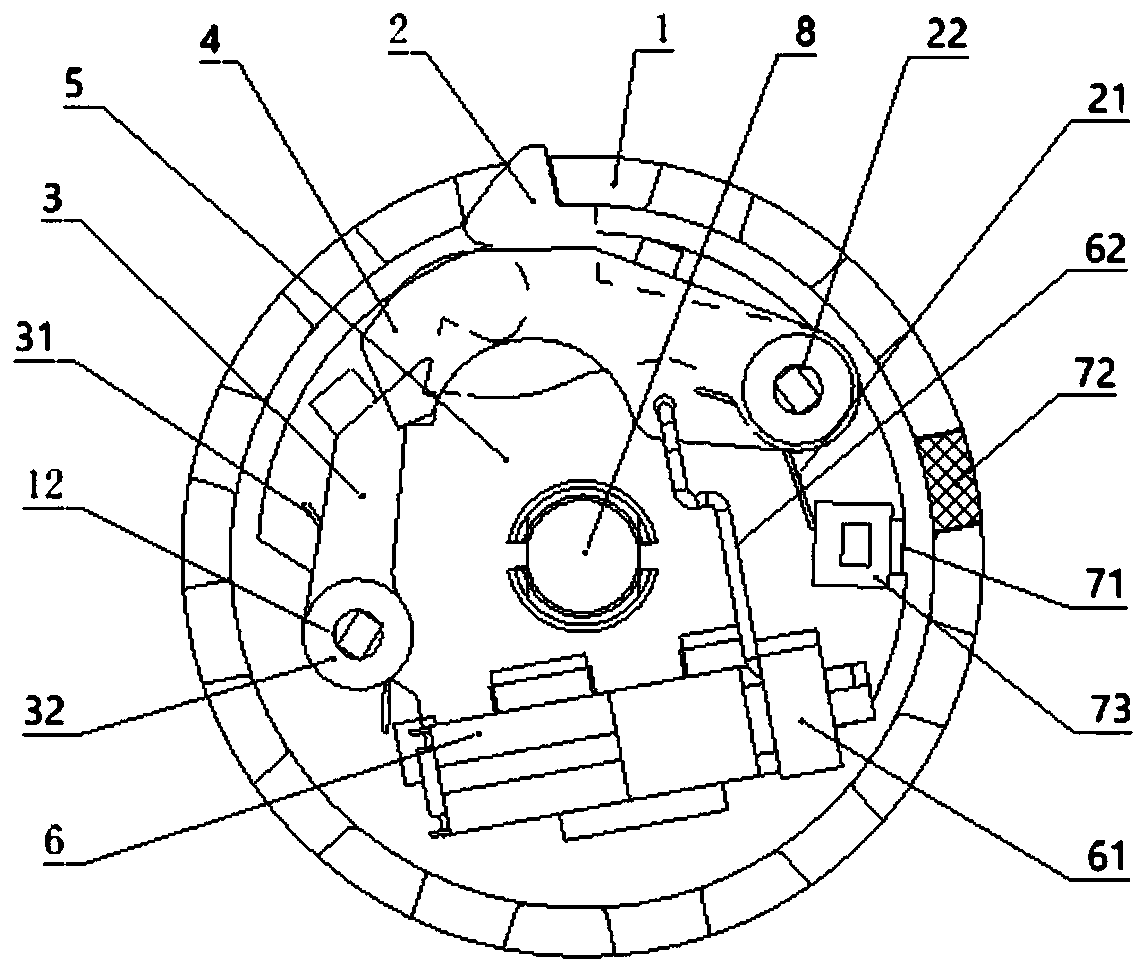
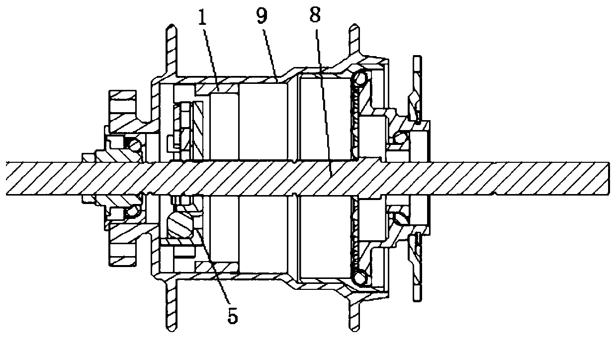
[0066] see figure 1 and figure 2 , a bicycle lock in the illustration is a preferred embodiment of the present invention, which adopts the rotation locking mechanism of the present invention to lock and unlock the hub 9 of the bicycle to realize the bicycle lock function.

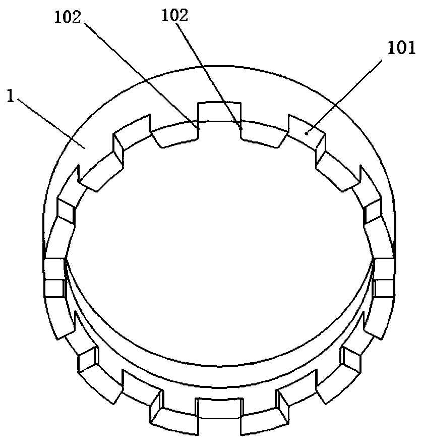
[0067] The rotation lock mechanism specifically includes components such as a rotation output member 1 , a first lock member 2 , a second lock member 3 , a switch member 4 , a mounting seat 5 , and a motor 6 .

[0068] Wherein the rotating output part 1 is used as the locking object between the rotating moving part and the locking mechanism, and is coaxially fixedly connected with the rotating moving part that needs to be locked. The rotating moving part in this embodiment is the hub 9 of the bicycle, and the hub is The spokes of the bicycle wheel and the rotating connector of the bicycle axle, the rotational power of the bicycle is transmitted to the hub 9, and then transmitted to the wheel through the h...

Embodiment 2

[0106] see in conjunction Figure 15 and Figure 16 , the difference between this embodiment and Embodiment 1 is that the first lock 2 in this embodiment is provided with a locking bayonet, the second lock 3 is provided with a locking angle, and the second lock 3 The rebound direction of the torsion spring of 3 is opposite to that of embodiment 1. During the unlocking process, the switch part 4 pushes the second lock part 3 to continue to swing clockwise. This solution is also within the protection scope of the claims of the present invention.


PUM


Abstract

The invention discloses a rotation locking mechanism and its applied car lock and locking control method. The rotation output part is locked through a stable triangular support structure between the first lock part and the second lock part. The second lock The effective restraint of the first lock piece by the piece in both the locked state and the unlocked state realizes the locking and unlocking reliability of the product. And the entire locking mechanism is controlled by the same switch, so the control process is more compact and effective. From the mechanical structure and automatic control method, it can effectively avoid the wrong locking operation of the rotating parts during operation, the locking reliability is high, and the use is simple and convenient. The entire rotating locking mechanism can be packaged and fixed in the car lock housing, and it can be used in bicycles. , electric vehicles, motorcycles and even light vehicles on the transmission machinery.

Description

technical field [0001] The invention belongs to mechanical locking technology, and in particular relates to a rotary locking mechanism and a vehicle lock and a locking control method thereof. Background technique [0002] At present, most of the locks such as bicycles, electric vehicles, and motorcycles adopt a mechanical locking structure to externally lock the wheels. At present, there are various bicycle locks on the market, including manual key locks or combination locks, etc. With the rise of public bicycle rental, there has been a public bicycle lock controlled by electric power, which also uses an external lock. The locking structure drives the corresponding locks through the automatically controlled motor to lock the wheels. [0003] This type of external locking structure is simple, requires a large number of external locking products, poor portability, high cost, and the locking reliability is not strong, it is easy to be damaged, and there are great hidden danger...

Claims


Application Information

Patent Timeline
Patent Type & Authority Patents(China)
IPC IPC(8): B62H5/16E05B15/00
CPCB62H5/142E05B15/00B62H5/148E05B71/00B60R25/02E05B17/2088E05B17/186E05B2047/0017B62H3/02E05B47/0012
Inventor 李激初
Owner GUANGDONG LOFANDI INTELLIGENT TECH CO LTD
Learn More