Board tensile deformation based robot bending precision compensating method

A technology of tensile deformation and precision compensation, applied in the direction of instruments, simulators, computer control, etc., can solve the problem of low bending accuracy of robots, and achieve the effect of eliminating pulling or squeezing and improving bending accuracy.

Active Publication Date: 2018-06-08
NANJING ESTUN ROBOTICS CO LTD
View PDF7 Cites 5 Cited by
  • Summary
  • Abstract
  • Description
  • Claims
  • Application Information

AI Technical Summary

Problems solved by technology

[0004] The technical problem to be solved by the present invention is to overcome the defects existing in the prior art, and propose a robot bending accuracy compensation method based on sheet metal tensile deformation, which solves the problems caused by sheet material tensile deformation during the bending process. The problem of low bending precision of robots, improve the bending precision of robots

Method used


Image

  • Board tensile deformation based robot bending precision compensating method
  • Board tensile deformation based robot bending precision compensating method
  • Board tensile deformation based robot bending precision compensating method

Examples


Embodiment Construction

[0045] The present invention will be described in detail below in conjunction with the embodiments and accompanying drawings.

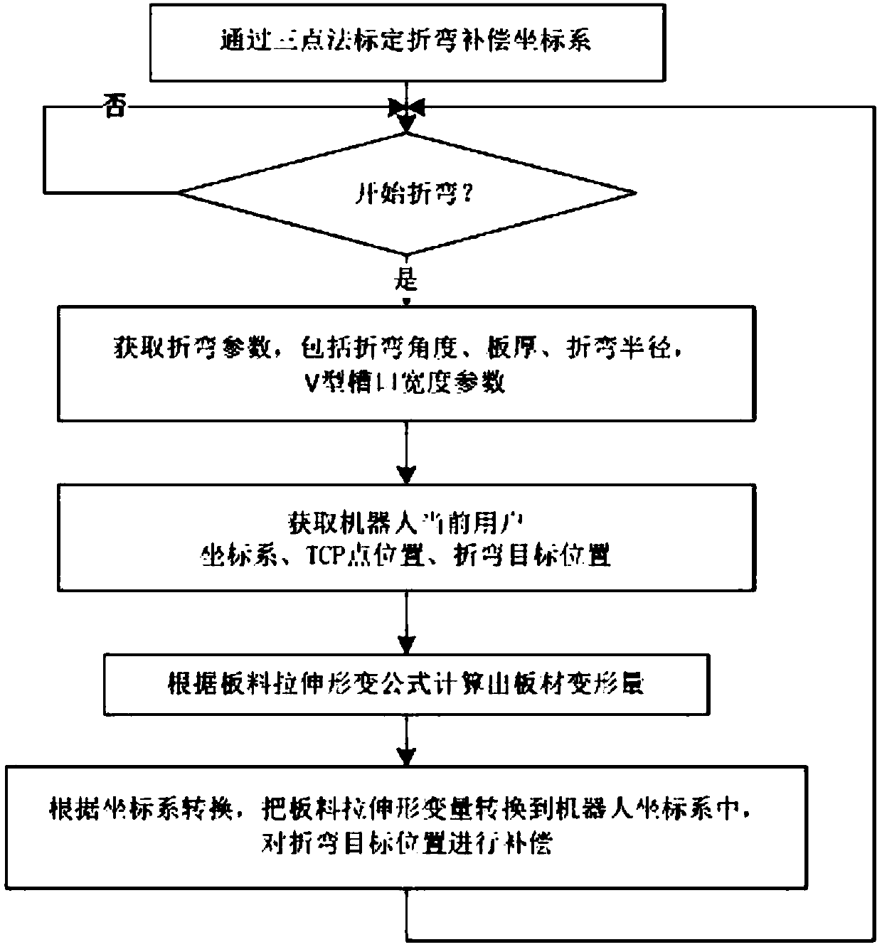
[0046] The implementation steps are as follows:

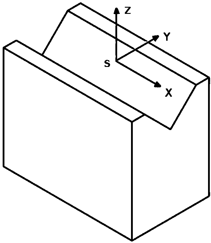
[0047] Step 1: Use the robot to calibrate the three points on the notch, and the coordinate value of the origin O is P O (1896.72, -239.85, 1033.50), calibrate the point P in the X-axis direction of the compensation coordinate system along the slot direction A (1835.10, -1672.77, 1038.03), point P in the XY plane direction of the calibration compensation coordinate system B (1856.89, -1437.79, 1037.22), calculate the X, Y, Z axis unit vectors of the compensation coordinate system respectively, and obtain the rotation matrix as follows:

[0048]

[0049] According to the Z-Y-Z Euler transformation formula, the rotation matrix R S Calculate A=-92.46, B=0, C=0, and thus obtain the compensation coordinate system as follows:

[0050] S=(1896.72, -239.85, 1033.50, -92.46, 0, 0)

[0051] Step 2: Obtai...


PUM


Abstract

The invention discloses a board tensile deformation based robot bending precision compensating method. First, a compensation coordinate system S is established in a V-shaped notch of a bending machine; bending parameters set by a user are acquired; after bending tracking is started, a user coordinate system CS (X, Y, Z, A, B, C) of a current robot system and robot TCP position P1 (X, Y, Z, A, B, C) are acquired and a bending target position P2 (X, Y, Z, A, B, C) is acquired; board tensile deformation during the board bending process is calculated and compensation of a compensation coordinate system S' is converted to be in the user coordinate system CS and is then compensated to the position P2, so that the new target position P2' subjected to compensation is acquired. According to the invention, board tensile deformation generated in a bending process is taken into account fully and board deformation is compensated to the target position tracked by the robot, pulling or extrusion on the board by the robot during the bending tracking process is eliminated and the bending precision is improved.

Description

technical field [0001] The invention relates to a bending industrial robot, in particular to a method for compensating the bending accuracy of the bending robot. Background technique [0002] With the continuous reduction of labor resources and the continuous increase of labor costs, in the field of bending, the demand for robot bending applications is becoming more and more urgent. At present, the accuracy of the robot has met the bending application, but the sheet material is deformed due to being stretched during the bending process, which causes the robot to pull or squeeze the sheet material to a certain extent after the bending is completed, which affects the bending accuracy. [0003] A Chinese invention patent application "Robot bending real-time following method and its device" (CN104475504A) document proposes a bending real-time following method, which uses an external detection device to pre-collect the bending knife displacement in a specific period, and then Ca...

Claims


Application Information

Patent Timeline
Patent Type & Authority Applications(China)
IPC IPC(8): G05B19/404
CPCG05B19/404G05B2219/35362
Inventor 宋方方敬淑义王杰高
Owner NANJING ESTUN ROBOTICS CO LTD
Why Eureka
Try Eureka