
Plate trimming device

A technology of edge cutting and sheet metal, which is applied in the direction of shearing devices, knives for shearing machine devices, manufacturing tools, etc., can solve problems affecting the processing quality of sheet metal, equipment life, physical and mental health of workers, and low production efficiency, so as to ensure the quality of sheet metal The effect of processing quality and physical and mental health of workers, improving work efficiency and saving manpower

Inactive Publication Date: 2019-03-15
重庆仁实商贸有限公司
View PDF6 Cites 0 Cited by
  • Summary
  • Abstract
  • Description
  • Claims
  • Application Information

AI Technical Summary

Problems solved by technology

[0004] The purpose of the present invention is to provide a board edge trimming device to solve the need to manually place the board on the cutting machine to saw off the four sides in order to solve the problem of cutting the board, resulting in low production efficiency; if the dust is not handled in time, it will easily affect the processing quality of the board, equipment life and the physical and mental health of the workers. health problems

Method used


Image

  • Plate trimming device
  • Plate trimming device

Examples


Embodiment Construction

[0014] The present invention will be described in further detail below by means of specific embodiments:

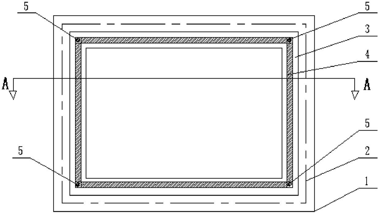
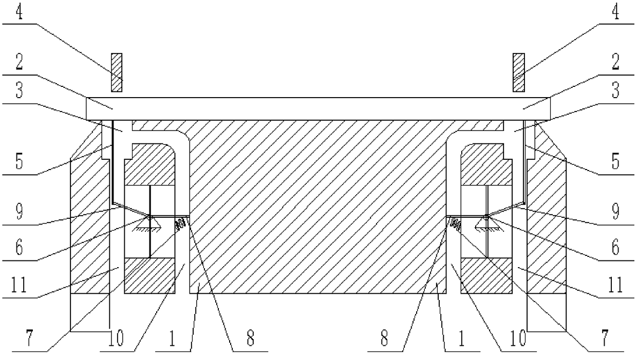
[0015] Instructions attached Figures 1 to 2 The reference signs in include: workbench 1, plate 2, groove 3, cutter 4, push rod 5, toggle switch 6, spring 7, driven plate 8, active plate 9, pipe 10, through hole 11.

[0016] Such as figure 1 As shown, the plate edge trimming device includes a workbench 1, a knife rest and a frame. The workbench 1 is located directly below the knife rest. The knife rest is a cuboid structure. The pulley and the knife rest are slidingly connected on the frame, and the four sides at the bottom of the knife rest are equipped with a cutter 4, the cutter 4 has an inclined cutting edge, and the knife rest is provided with a driving mechanism for driving the cutter 4 to move up and down. Such as figure 2 As shown, the workbench 1 is provided with a groove 3 for inserting the cutter 4, and the bottom of the groove 3 is provided with a through ...


PUM


Abstract

The invention belongs to the technical field of sheet processing and particularly discloses a plate cutting device, including a workbench, a tool rack and a rack. The workbench is located right belowthe tool rack. The tool rack is a rectangular structure. The four sides of the bottom of the tool rack are provided with cutting tools. A driving mechanism used for driving the cutting tools to move up and down is arranged on the tool rack. Grooves are arranged on the workbench. The bottom of the groove is provided with through holes. One side of the groove is communicated with a channel running through the bottom of the workbench. One end of the channel is connected with an air supply device. The interior of the workbench is provided with a cavity. A clapboard is arranged in the cavity. The clapboard is connected with a toggle switch in hinge. The toggle switch includes an active plate and a driven plate. The active plate is fixedly connected with the driven plate. The active plate is inserted into the through holes. A push rod capable of driving the active plate to move downward is arranged on the tool rack. The length of the push rod is longer than the length of the cutting tool. The driven plate is inserted into the channel. The driven plate is connected with a spring. The adoption of the plate cutting device can improve the production efficiency of the plate, the processing quality of the plate and the service life of the device, and protect workers' physical and mental health.

Description

technical field [0001] The invention belongs to the technical field of plate processing, in particular to a plate trimming device. Background technique [0002] Plates are made into standard-sized flat rectangular building material plates, which are used in the construction industry as components of walls, ceilings or floors, and mostly refer to forged, rolled or cast metal plates, which are divided into thin plates, medium Boards, thick boards, extra thick boards, flat rectangular building material boards usually made into standard sizes. However, in the existing plate production, in the final stage of processing, the periphery of the plate will be rough and have burrs, which do not meet the product requirements, so the periphery of the plate is usually cut. [0003] However, the existing cutting tool is an ordinary cutting machine, which needs to be manually placed on the cutting machine to saw off the four sides in sequence, and more dust is generated during the cutting ...

Claims


Application Information

Patent Timeline
Patent Type & Authority Patents(China)
IPC IPC(8): B23D15/06B23D35/00B23Q11/00
CPCB23D15/06B23D35/001B23D35/002B23Q11/005
Inventor 刘桂禄
Owner 重庆仁实商贸有限公司
Learn More