
Overload protection system and overload protection method suitable for Stirling engine

A Stirling engine and overload protection technology, which is applied to machines/engines, hot gas variable capacity engine devices, mechanical equipment, etc. The effect of high output power and high solar energy utilization

Active Publication Date: 2018-06-05
AECC AVIATION POWER CO LTD
View PDF7 Cites 0 Cited by
  • Summary
  • Abstract
  • Description
  • Claims
  • Application Information

AI Technical Summary

Problems solved by technology

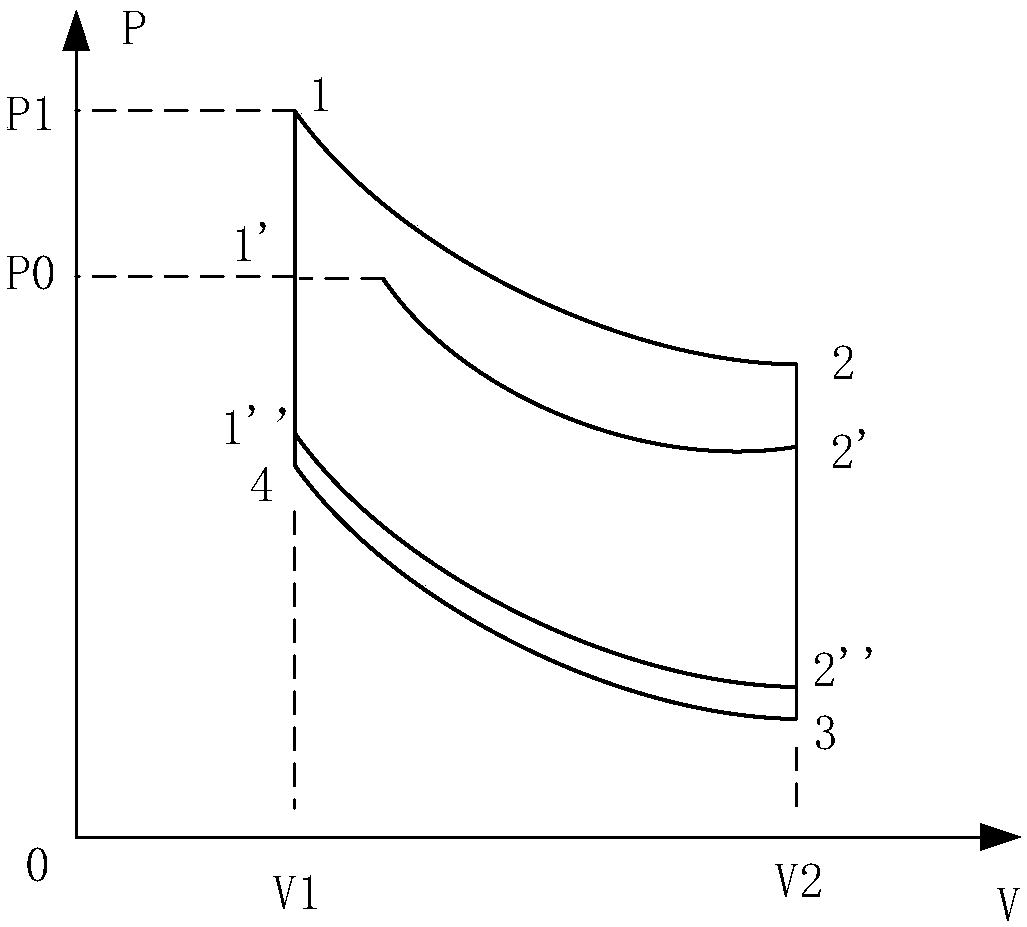
[0003] The current overload protection of the Stirling engine is mostly realized by cutting off the heat, changing the original cycle from 1→2→3→4 to 1″→2″→3→4, so that not only the engine output power has dropped significantly , and in the process of cutting off the heat, the solar energy is not utilized, which reduces the economical efficiency of the power station

Method used


Image

  • Overload protection system and overload protection method suitable for Stirling engine
  • Overload protection system and overload protection method suitable for Stirling engine

Examples


Embodiment Construction

[0017] The technical solutions in the embodiments of the present invention will be clearly and completely described below in conjunction with the accompanying drawings in the embodiments of the present invention. The embodiments described herein are only part of the embodiments of the present invention, not all of them. Based on the embodiments of the present invention, all other embodiments obtained by persons of ordinary skill in the art without creative efforts fall within the protection scope of the present invention.

[0018] Such as figure 2 As shown, the present invention is suitable for the overload protection system of the Stirling engine, which includes an air storage tank communicated with the hot chamber of the Stirling engine, the inside of the air storage tank has a piston and a spring that provides pre-tightening force for the piston, and stores the gas Both the air inlet and the exhaust port of the tank are connected with the thermal cavity of the Stirling eng...


PUM


Abstract

The invention discloses an overload protection system and an overload protection method suitable for a Stirling engine. The protection system comprises a gas storage tank communicated with a thermal chamber of the Stirling engine. When the internal pressure of the Stirling engine exceeds P0, high temperature and high pressure gas in the engine is under constant pressure and enters the gas storagetank; and when the internal pressure of the Stirling engine is lower than P0, the high pressure gas is under constant pressure and enters the thermal chamber of the engine, which plays a role of overload protection of the engine. Solar energy is absorbed and utilized by arranging the gas storage tank, and compared with a direct heat removal method, the method makes the solar energy utilization rate higher and makes the output power of the engine higher.

Description

technical field [0001] The invention belongs to the Stirling engine technology, and relates to the Stirling engine overload protection technology, in particular to an overload protection system and an overload protection method suitable for the Stirling engine. Background technique [0002] The P-V diagram of the Stirling engine cycle is as follows figure 1 As shown, it can be seen from the figure that P1 is the highest pressure of the cycle, assuming that the pressure value of this state point exceeds the maximum pressure P0 allowed by the engine, then overload occurs. [0003] The current overload protection of the Stirling engine is mostly realized by cutting off the heat, changing the original cycle from 1→2→3→4 to 1″→2″→3→4, so that not only the engine output power has dropped significantly , And in the process of cutting off the heat, the solar energy is not utilized, which reduces the economy of the power station. Contents of the invention [0004] In view of the ...

Claims


Application Information

Patent Timeline
Patent Type & Authority Applications(China)
IPC IPC(8): F02G1/045F02G1/053
CPCF02G1/045F02G1/053
Inventor 黄汉林徐国成张海涛田文静杨文革张永楠王明明陈常征
Owner AECC AVIATION POWER CO LTD
Learn More