Novel bridge maintenance facility

A technology for bridges and facilities, applied in the field of new bridge maintenance facilities, can solve the problems of inability to adjust the speed of flushing, poor cleaning effect, low efficiency, etc., and achieve the effect of reducing labor costs, reducing labor operations, and improving work efficiency

Inactive Publication Date: 2018-06-05
广西南宁旭兆建筑工程技术有限公司
View PDF4 Cites 0 Cited by
  • Summary
  • Abstract
  • Description
  • Claims
  • Application Information

AI Technical Summary

Problems solved by technology

In the daily maintenance of bridges, the cleaning of the road surface is particularly basic. Small bridges are generally cleaned by manual watering. This method is time-consuming, laborious, and inefficient. Some automatic cleaning vehicles cannot simultaneously clean the road surface and the facilities on both sides of the bridge. Rinse, can not adjust the speed of rinsing, the cleaning effect is not good

Method used


Image

  • Novel bridge maintenance facility
  • Novel bridge maintenance facility
  • Novel bridge maintenance facility

Examples


Embodiment Construction

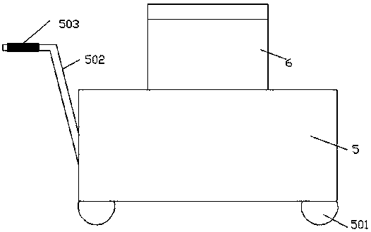
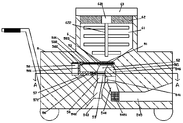
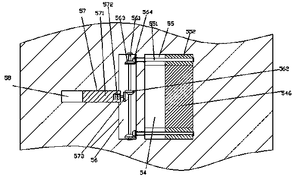
[0027] Such as Figure 1-Figure 8As shown, a novel bridge maintenance facility of the present invention includes a body 5 and a liquid storage tank 6 installed on the top of the body 5, the liquid storage tank 6 is provided with a downwardly extending liquid storage chamber 61, The extended section at the bottom of the liquid storage chamber 61 penetrates into the body 5, and the body 5 at the end of the bottom of the liquid storage chamber 61 is provided with an infusion port 51 at the top that communicates with the liquid storage chamber 61. The infusion port 51 is provided with a left and right elongated sliding cavity 53, the sliding cavity 53 is provided with a sealing control device, the bottom of the infusion port 51 communicates with the accommodating cavity 52, and the bottom of the accommodating cavity 52 Unicom is provided with an infusion chamber 54, and the middle part of the bottom of the infusion chamber 54 is provided with a dividing plate 541 fixedly connected...


PUM


Abstract

The invention discloses a novel bridge maintenance facility. The novel bridge maintenance facility comprises a machine body and a liquid storage tank installed on the top of the machine body, the liquid storage tank is internally provided with a liquid storage cavity extending downwards, the extending section of the bottom of the liquid storage cavity stretches into the machine body, a liquid transport opening with the top communicated with the liquid storage cavity is formed in the portion, at the tail of the bottom of the liquid storage cavity, in the machine body, a sliding cavity extendingleftwards and rightwards runs through the liquid transport opening, a sealing control device is arranged in the sliding cavity, a containing cavity communicated with the bottom of the liquid transport opening is formed in the sliding cavity, the bottom of the containing cavity is communicated with the liquid transportation cavity, a division plate fixedly connected with the front inner wall and the rear inner wall of the liquid transport cavity is arranged in the middle in the bottom of the liquid transport cavity, a sliding block is in smooth matching connection with the portion, in the liquid transport cavity, of the top of the division plate, and a conical slider which stretches into the containing cavity and is in smooth matching connection with the containing cavity is fixedly arranged on the top of the sliding block. The novel bridge maintenance facility is simple in structure, convenient to operate, capable of improving the cleaning efficiency, good in cleaning effect, capableof lowering labor intensity, time-consuming and labor-consuming in use and capable of meeting various cleaning requirements.

Description

technical field [0001] The invention relates to the field of bridge maintenance, in particular to a novel bridge maintenance facility. Background technique [0002] Bridges are not only important transportation links, but also become an integral part of the landscape everywhere. In the daily maintenance of bridges, the cleaning of the road surface is particularly basic. Small bridges are generally cleaned by manual watering. This method is time-consuming, laborious, and inefficient. Some automatic cleaning vehicles cannot simultaneously clean the road surface and the facilities on both sides of the bridge. Rinsing, can not adjust the speed of rinsing, cleaning effect is not good. Contents of the invention [0003] The technical problem to be solved by the present invention is to provide a new type of bridge maintenance facility, which can solve the above-mentioned problems in the prior art. [0004] The present invention is achieved through the following technical soluti...

Claims


Application Information

Patent Timeline
Patent Type & Authority Applications(China)
IPC IPC(8): E01H1/00E01H1/10
CPCE01H1/005E01H1/101
Inventor 朱江帆
Owner 广西南宁旭兆建筑工程技术有限公司
Why Eureka
Try Eureka