Automatic assembling device used for assembling steel balls and steel pins simultaneously and assembling method of automatic assembling device

An automatic assembly and steel ball technology, applied in metal processing, metal processing equipment, manufacturing tools, etc., can solve the problems of low placement efficiency, high number of grabs, low alignment, etc., and achieve the effect of continuous reclaiming.

Active Publication Date: 2018-06-05
ZHEJIANG YAT ELECTRICAL APPLIANCE CO LTD
View PDF10 Cites 2 Cited by
  • Summary
  • Abstract
  • Description
  • Claims
  • Application Information

AI Technical Summary

Problems solved by technology

[0002] During the assembly process of electric tools, steel balls and steel pins are usually assembled. In the traditional assembly process, the steel balls and steel pins are assembled by the operator manually placing the steel balls or steel pins into the predetermined holes. There are problems with this assembly process. First, the number of steel balls and steel pins is often large, and the volume is relatively small. The operator often encounters the problem of too many times of grabbing and difficult grabbing during the grabbing process. Second, In the process of placing the grasped steel ball or steel pin into the predetermined hole, the operator will also encounter the problems of poor alignment and low placement efficiency

Method used


Image

  • Automatic assembling device used for assembling steel balls and steel pins simultaneously and assembling method of automatic assembling device
  • Automatic assembling device used for assembling steel balls and steel pins simultaneously and assembling method of automatic assembling device
  • Automatic assembling device used for assembling steel balls and steel pins simultaneously and assembling method of automatic assembling device

Examples


Embodiment Construction

[0030] The technical solutions of the embodiments of the present invention will be explained and described below in conjunction with the accompanying drawings of the embodiments of the present invention, but the following embodiments are only preferred embodiments of the present invention, not all of them. Based on the examples in the implementation manners, other examples obtained by those skilled in the art without making creative efforts all belong to the protection scope of the present invention.

[0031] In the following description, terms such as "inner", "outer", "upper", "lower", "left", "right", etc. that indicate orientation or positional relationship are based on the orientation or positional relationship shown in the drawings, It is only for the convenience of describing the embodiment and simplifying the description, but does not indicate or imply that the device or element referred to must have a specific orientation, be constructed and operated in a specific orie...


PUM


Abstract

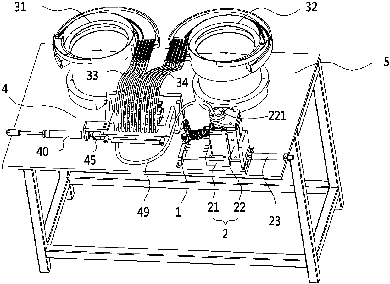
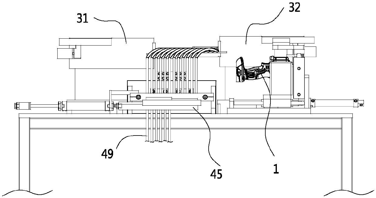
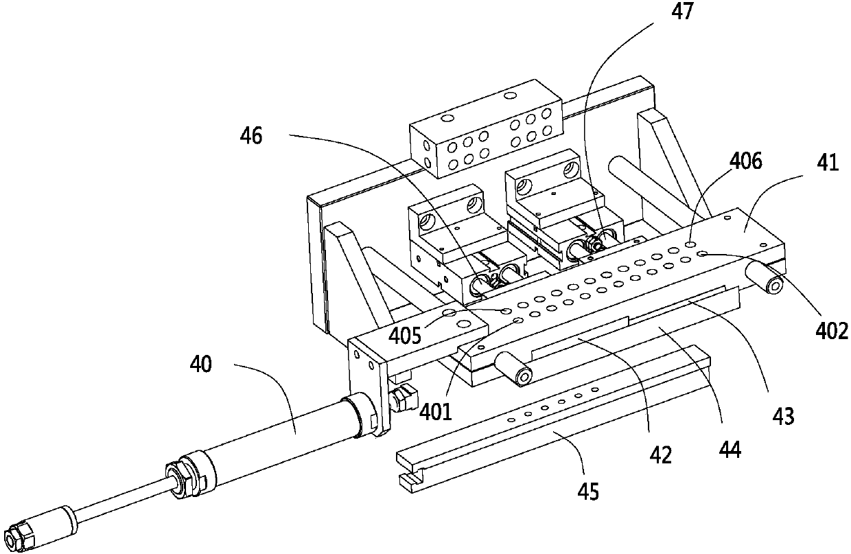
The invention discloses an automatic assembling device used for assembling steel balls and steel pins simultaneously, and belongs to the technical field of automatic tools. The automatic assembling device comprises a positioning base used for positioning a to-be-installed workpiece, the automatic assembling device further comprises a first vibrating disc for containing the steel balls and a secondvibrating disc for containing the steel pins, the first vibrating disc and the second vibrating disc feed the steel balls and the steel pins to a receiving device through vibration feeding, a feedingplate is movably installed in the receiving device and is connected with a first driver and a feeding pipe, the motion positions of the feeding plate in the receiving device comprise a first positionand a second position, when the feeding plate is at the first position, the steel balls are conveyed into the to-be-installed workpiece through the feeding pipe, and when the feeding plate is locatedat the second position, the steel pins are conveyed into the to-be-installed workpiece through the feeding pipe. In addition, the invention further discloses an assembling method for assembling the steel balls and the steel pins simultaneously through the automatic assembling device. The automatic assembling device and the assembling method can greatly improve the assembling efficiency and the assembly accuracy.

Description

【Technical field】 [0001] The invention relates to an automatic assembler for simultaneously assembling steel balls and steel pins and an assembly method thereof, belonging to the technical field of automatic tooling. 【Background technique】 [0002] During the assembly process of electric tools, steel balls and steel pins are usually assembled. In the traditional assembly process, the steel balls and steel pins are assembled by the operator manually placing the steel balls or steel pins into the predetermined holes. There are problems with this assembly process. First, the number of steel balls and steel pins is often large, and the volume is relatively small. The operator often encounters the problem of too many times of grabbing and difficult grabbing during the grabbing process. Second, In the process of placing the grasped steel ball or steel pin into the predetermined hole, the operator also encounters the problems of poor alignment and low placement efficiency. 【Conte...

Claims


Application Information

Patent Timeline
Patent Type & Authority Applications(China)
IPC IPC(8): B23P19/00
CPCB23P19/001
Inventor 孙兴来孙建来沈雁卿
Owner ZHEJIANG YAT ELECTRICAL APPLIANCE CO LTD
Why Eureka
Try Eureka