
Electromagnetic valve

A technology of electromagnetic valve and electromagnetic mechanism, applied in the field of electromagnetic valve, can solve the problems of increasing the cost of the electromagnetic valve, the complex structure of the pressure reducing valve, increasing the overall volume and complexity of the electromagnetic valve, etc. Effect

Active Publication Date: 2018-06-01
浙江康乐达新能源有限公司
View PDF6 Cites 3 Cited by
  • Summary
  • Abstract
  • Description
  • Claims
  • Application Information

AI Technical Summary

Problems solved by technology

[0003] For the existing solenoid valve, if you want to achieve a constant pressure of the medium at the medium outlet, you need to install a pressure reducing valve. However, the traditional pressure reducing valve has a complex structure and is an independent structure, which cannot be integrated with other structures. Together, in this way, the solenoid valve needs to be separately installed with a pressure reducing valve structure, which not only increases the overall volume and complexity of the solenoid valve, but also increases the cost of the solenoid valve

Method used


Image

  • Electromagnetic valve
  • Electromagnetic valve
  • Electromagnetic valve

Examples


Embodiment Construction

[0057] The present application will be described in further detail below through specific embodiments and in conjunction with the accompanying drawings.

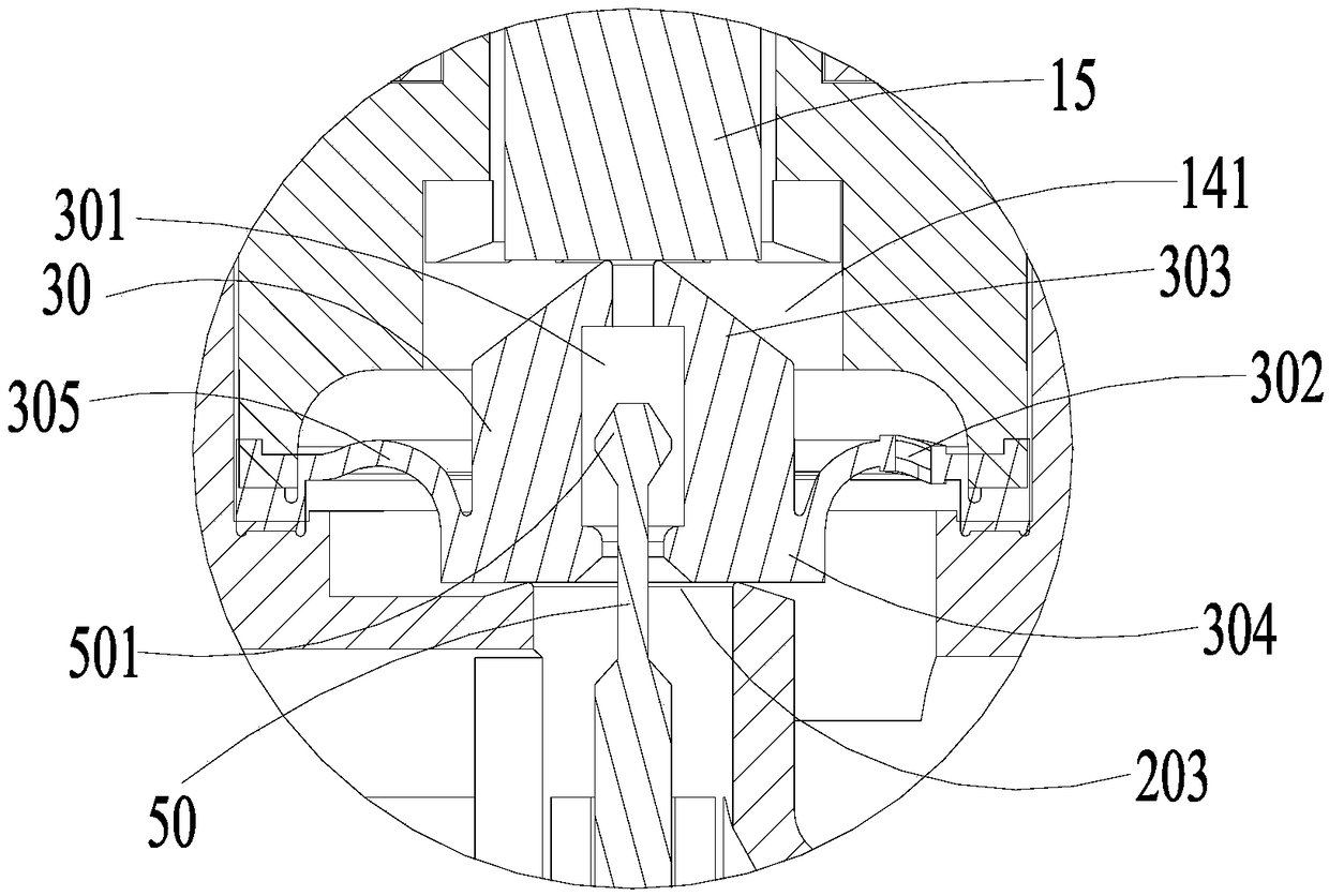
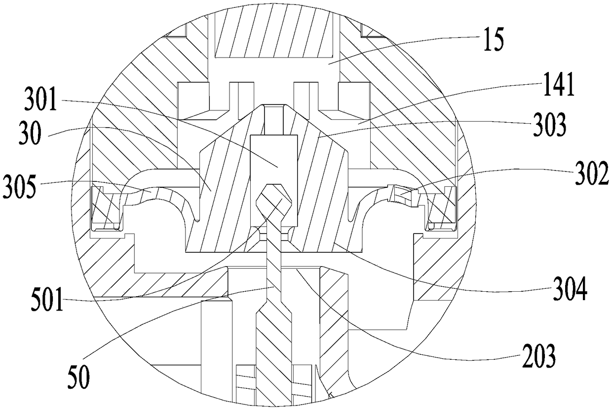
[0058] Such as Figure 1-3 As shown, the embodiment of the present application provides a solenoid valve, including a valve body 20 , an electromagnetic mechanism 10 , a valve body diaphragm 30 , a connecting rod 50 and a decompression diaphragm 40 .

[0059] The valve body 20 includes a medium inlet 201, a medium outlet 202 and a main valve port 203. The main valve port 203 communicates with the medium outlet 202, and the medium outlet 202 can communicate with the medium inlet 201 through the main valve port 203. Generally, the medium inlet 201 communicates with the medium The outlet 202 is separated by an isolation structure such as a partition, and the medium flow direction of the main valve port 203 is perpendicular to the medium inlet 201 and the medium outlet 202 .

[0060] The electromagnetic mechanism 10 is disposed...


PUM


Abstract

The application relates to the technical field of valves, in particular to an electromagnetic valve. The electromagnetic valve comprises a valve body, an electromagnetic mechanism, a valve body diaphragm, a connecting rod and a pressure-reducing diaphragm. The valve body diaphragm is arranged between a seat rack and a main valve opening. Additionally, the main valve opening is sealed or opened. The valve body diaphragm is equipped with a by-pass opening and a pilot hole. The connecting rod is slidably inserted into the pilot hole and comprises a blocking end and a connecting end. In the normalstate, the blocking end opens up the pilot hole. The connecting end is connected with the pressure-reducing diaphragm. The pressure-reducing diaphragm is arranged at one end where a medium outlet communicates with the main valve opening and opposite to the main valve opening. At least a part of the pressure-reducing diaphragm can slide along the axial direction of the pilot hole relative to the valve body. Only the valve body diaphragm and the pressure-reducing diaphragm are required to be added into the electromagnetic valve so that the pressure reduction effect is realized. Therefore, the electromagnetic valve and a pressure-reducing valve gather together. The electromagnetic valve has a simple structure. Without reinstalling the electromagnetic valve or increasing the size thereof, cost is lowered.

Description

technical field [0001] The present application relates to the technical field of valves, in particular to an electromagnetic valve. Background technique [0002] Solenoid valves on the market usually include a valve body and an electromagnetic mechanism. The valve body is provided with a medium inlet, a medium outlet and a main valve port, and the main valve port is connected to the medium outlet. The electromagnetic mechanism is installed on one side of the valve body, including a coil assembly, a seat The frame and the moving iron core, the coil assembly is installed in the seat frame, the seat frame is provided with an accommodating chamber with an opening facing the valve body, one end of the moving iron core is slidably installed in the accommodating chamber, and the other end can seal or open the main valve port. When working, the electromagnetic mechanism is energized, and the moving iron core moves to the side away from the valve body, opening the main valve port, so...

Claims


Application Information

Patent Timeline
IPC IPC(8): F16K7/17F16K31/06F16K31/126F16K39/02
CPCF16K7/17F16K31/0655F16K31/1268F16K39/024
Inventor 陈旭敏
Owner 浙江康乐达新能源有限公司
Learn More