
Axle travel locking device of vehicle

A locking device and axle technology, which is applied to axle suspension devices, bicycle accessories, transportation and packaging, etc., can solve the problems of large-scale car body and restrictions on generality, and achieve the purpose of ensuring the height from the ground, improving the degree of design freedom, avoiding the dumping effect

Active Publication Date: 2018-06-01
KYMCO
View PDF6 Cites 0 Cited by
  • Summary
  • Abstract
  • Description
  • Claims
  • Application Information

AI Technical Summary

Problems solved by technology

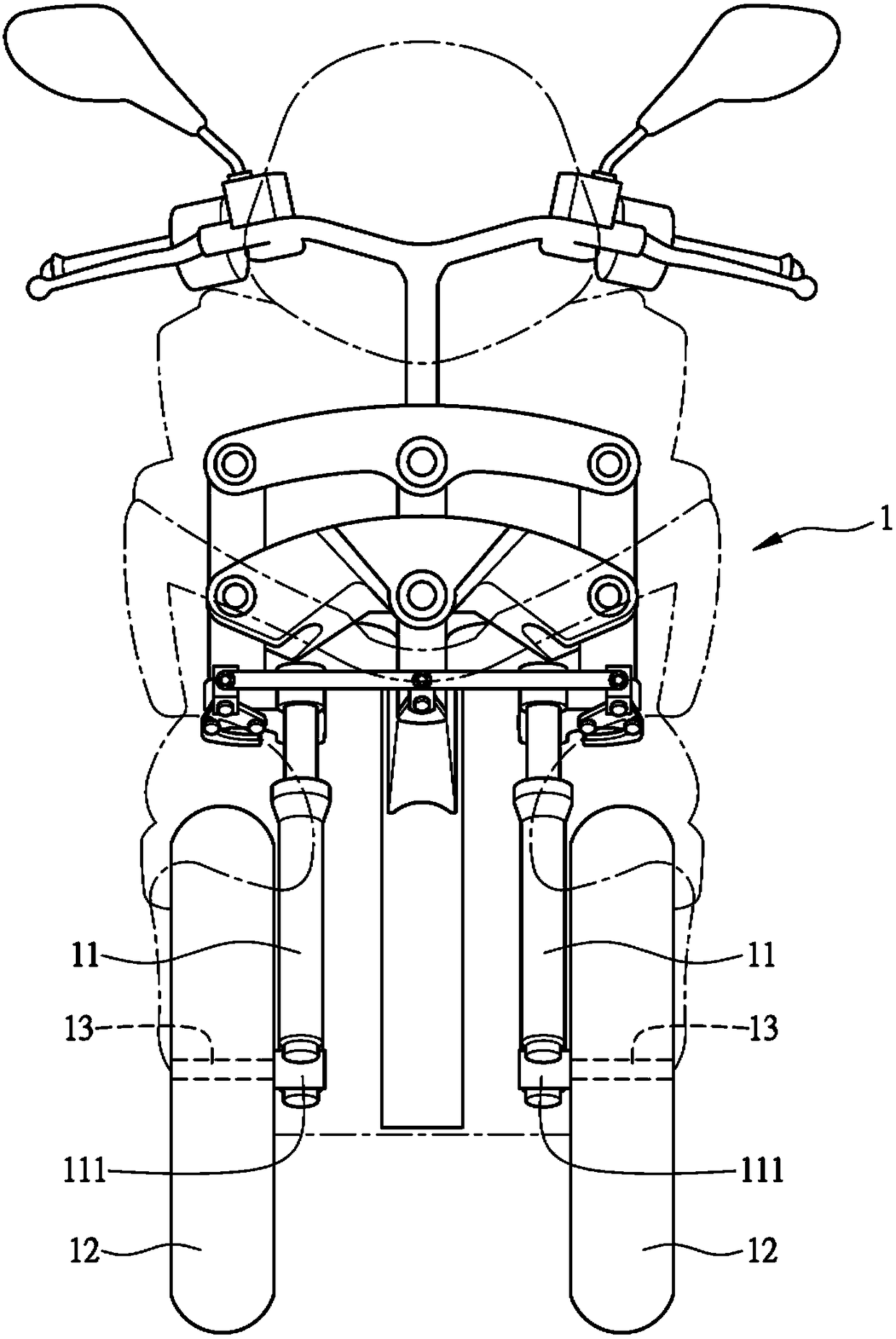
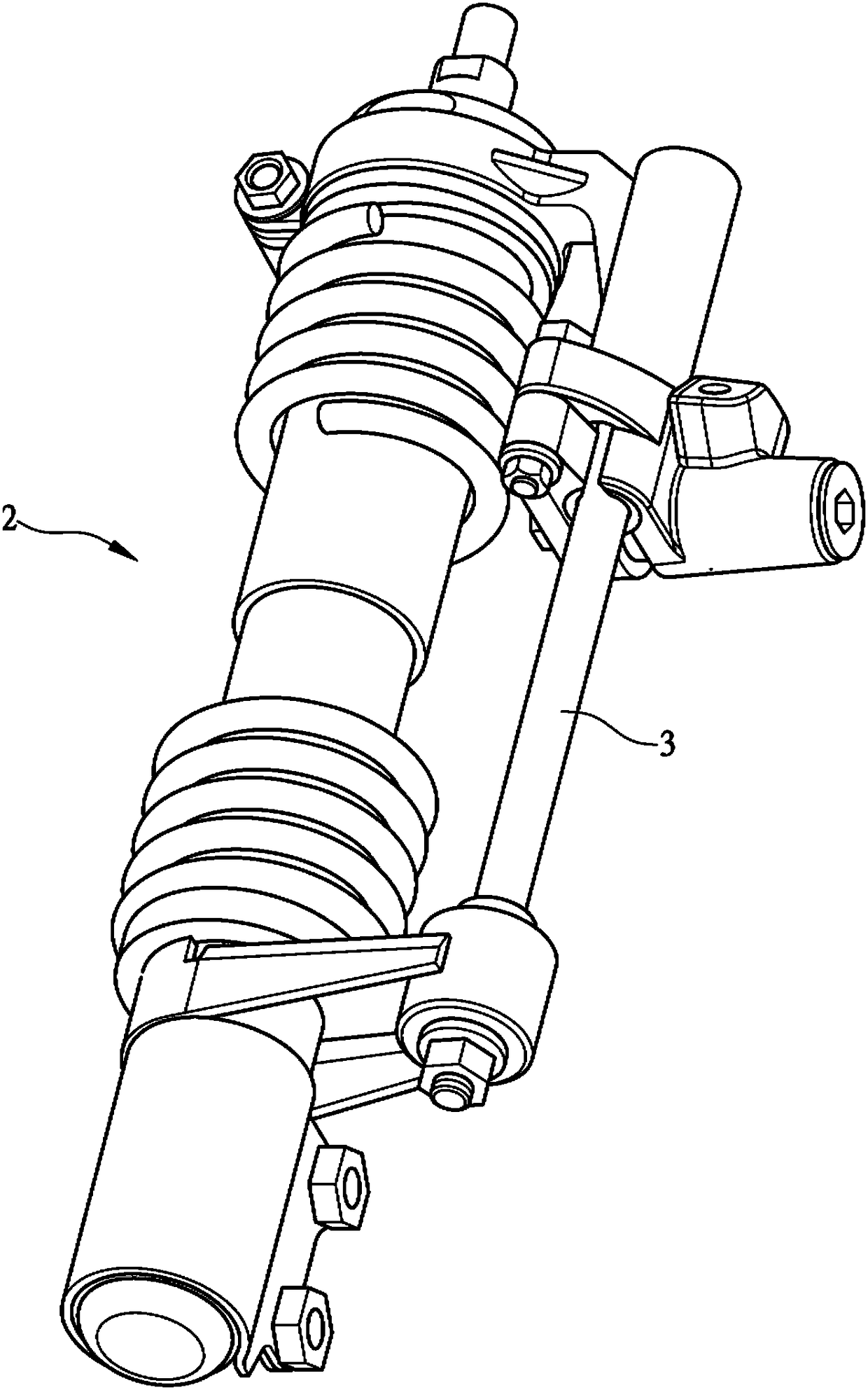
However, the upper and lower ends of the stroke stop device 3 are integrally connected to the upper and lower ends of the front fork unit 2, so the versatility of the front fork unit 2 and the stroke stop device 3 is severely limited; the TWI346054 The stroke stop device 3 of the invention patent is arranged on the outer side of a pair of left and right front wheels, thus resulting in the enlargement of the vehicle body in the left and right width direction of the TWI346054 invention patent

Method used


Image

  • Axle travel locking device of vehicle
  • Axle travel locking device of vehicle
  • Axle travel locking device of vehicle

Examples


Embodiment Construction

[0041] In order to understand the structure of the present invention and the effect that can be achieved more easily, the description is as follows in conjunction with the accompanying drawings;

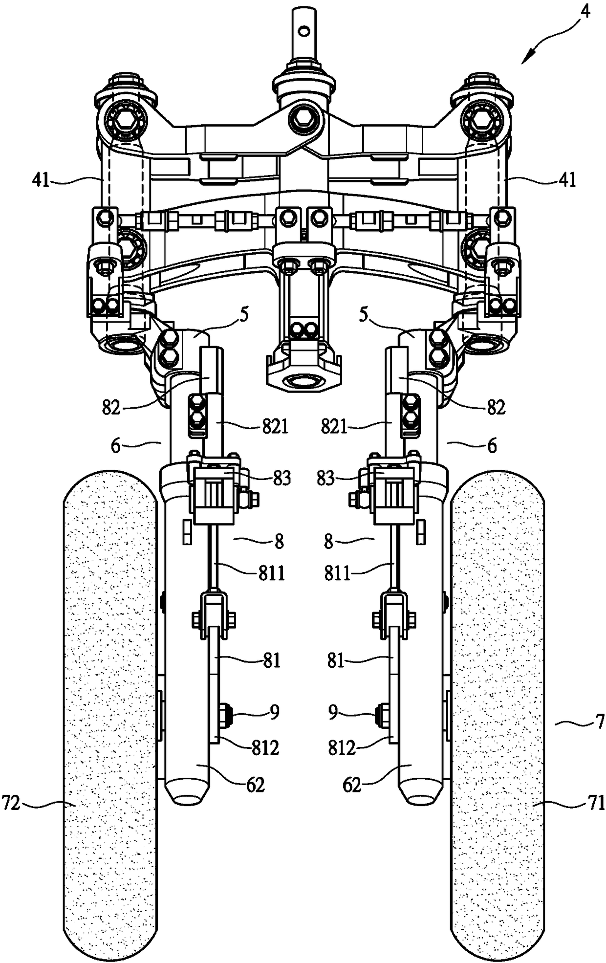
[0042] Such as image 3 , 4 As shown, the vehicle 4 at least includes a front fork support base 5, a front fork unit 6 whose upper end is supported on the front fork support base 5, a front wheel 7 pivotally arranged at the lower end of the front fork unit 6, and an upper end Linked to the front fork support base 5 and the lower end of which is linked to the axle stroke locking device 8 on the lower end of the front fork unit 6; the front wheel 7 has a left front wheel 71 and a right front wheel 72 arranged left and right, and the front wheel 7 has a hub 7a.

[0043] Such as image 3 , 4 As shown, the front fork support base 5 is located in front of the vehicle body 4, the upper end of the front fork support base 5 is connected to the steering mechanism 41 of the vehicle 4, and t...


PUM


Abstract

The invention relates to an axle travel locking device of a vehicle. The vehicle is at least equipped with a front fork support seat, front fork units, a front wheel, front fork support seats and an axle travel locking device. One upper ends of the front fork units are arranged on the front fork support seats. The front wheel is pivotally arranged at the lower ends of the front fork units throughaxles. The axle travel locking device is equipped with first connecting parts, second connecting parts and brake parts. The first connecting parts are provided with guide rods. The guide rods are arranged in a way that the first connecting parts extend towards the directions of the front fork support seats. Lower ends of the first connecting parts are arranged on the axles in a locking manner. Upper end sides of the second connecting parts are arranged on the front fork support seats in a locking manner. The guide rods can be arranged in the second connecting parts in a penetrating manner. Thebrake parts are connected to the second connecting parts and allow the guide rods of the first connecting parts to penetrate and limit the guide rods to slide. Through the first connecting parts andthe second connecting parts of the axle travel locking device, easy changes can be made. Therefore, the front fork units or the axle travel locking device is used more widely. As a result, the vehicleis designed more freely.

Description

technical field [0001] The present invention relates to a wheel shaft travel locking device of a vehicle, in particular to a wheel shaft travel locking device of a vehicle that can avoid the failure of a vehicle with two front wheels to overturn easily. Background technique [0002] Such as figure 1 As shown, a vehicle 1 with two front wheels is provided with a pair of left and right front fork units 11 at the front, and the lower end of the front fork unit 11 is provided with a wheel shaft pivoting portion 111, and the two front wheels 12 are pivotally mounted on the wheel shaft 13. The axle pivoting portion 111 is arranged so that the two front wheels 12 rotate around the axle 13 . [0003] However, when the vehicle 1 stops running or the rider is parked and causes the vehicle 1 to lean to one side due to his feet landing on the ground, one of the front fork units 11 of the left and right pairs of front fork units 11 will be compressed and contracted. , but the front for...

Claims


Application Information

Patent Timeline
IPC IPC(8): B62K25/04B62K25/08
CPCB62K25/04B62K25/08B62K2025/047
Inventor 丁信志李炎修黄碧松
Owner KYMCO
Learn More