
Hot riveting machining device

A processing device and hot riveting technology, which is applied to household components, household appliances, and other household appliances, etc., can solve problems such as hot riveting time adjustment, improvement of riveting effect, impact on product quality and production efficiency, etc., to achieve stable hot riveting quality, The effect of high heat riveting efficiency

Pending Publication Date: 2018-06-01
JIANGSU YEDI AUTOMOTIVE LIGHTING SYST
View PDF7 Cites 0 Cited by
  • Summary
  • Abstract
  • Description
  • Claims
  • Application Information

AI Technical Summary

Problems solved by technology

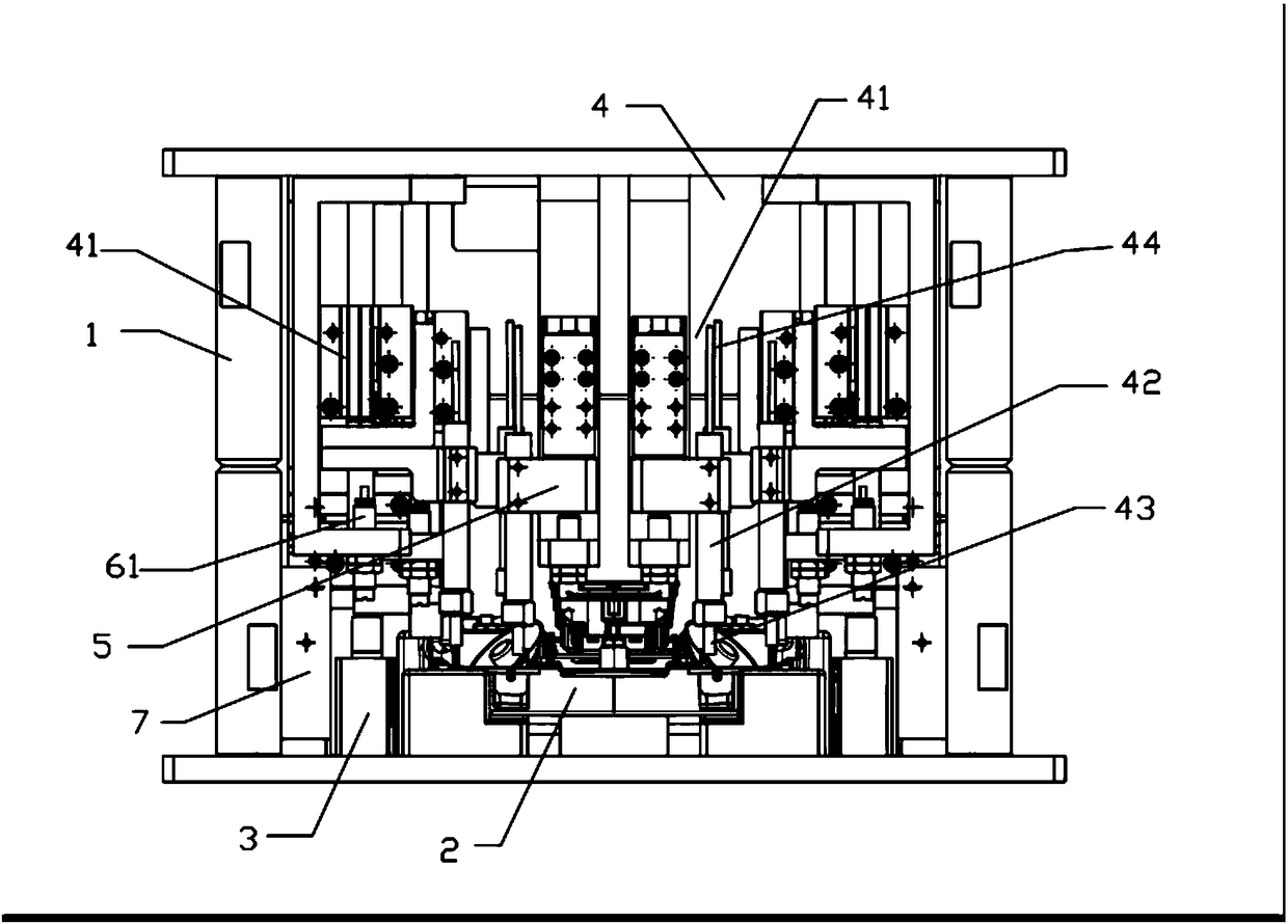
The tooling of the existing hot riveting processing equipment is processed from a whole piece of metal, and the riveting is heated by a built-in heating tube in the tooling. The position adjustment of the tooling in this type of equipment is only realized by rising and falling and only through one master cylinder. Since the hot riveting tooling is processed as a whole, multiple riveting points need to be riveted. If the welding effect of some riveting points is not ideal during the riveting process, the hot riveting temperature, hot riveting time and thermal The riveting position is adjusted to improve the riveting effect. If it needs to be dealt with, it can only be repaired manually, which seriously affects the product quality and production efficiency.

Method used


Image

  • Hot riveting machining device
  • Hot riveting machining device

Examples


specific Embodiment approach 1

[0017] Such as figure 1 , a workbench 2 is fixed below the frame 1, and the frame 1 above the workbench 2 is correspondingly provided with six sets of hot riveting processing units 4 which can simultaneously hot rivet six riveting points, and the workbench 2 is provided with fastening processing parts The clamping cylinder 3, the frame 1 is provided with a photoelectric switch 7 to control the work of the clamping cylinder 3, each group of hot riveting processing unit 4 includes a hot riveting cylinder 41 arranged on the frame, and the hot riveting cylinder 41 passes through the connecting block 5 The heating pipe 42 with the hot riveting head 43 facing the direction of the workbench 2 is connected at the end. Each hot riveting cylinder 41 corresponds to a limit buffer 61 which limits it and is arranged on the frame. The heating pipe 42 is connected with a temperature sensing line 44 connected with a temperature control device. The temperature of the heating tube and the tre...

specific Embodiment approach 2

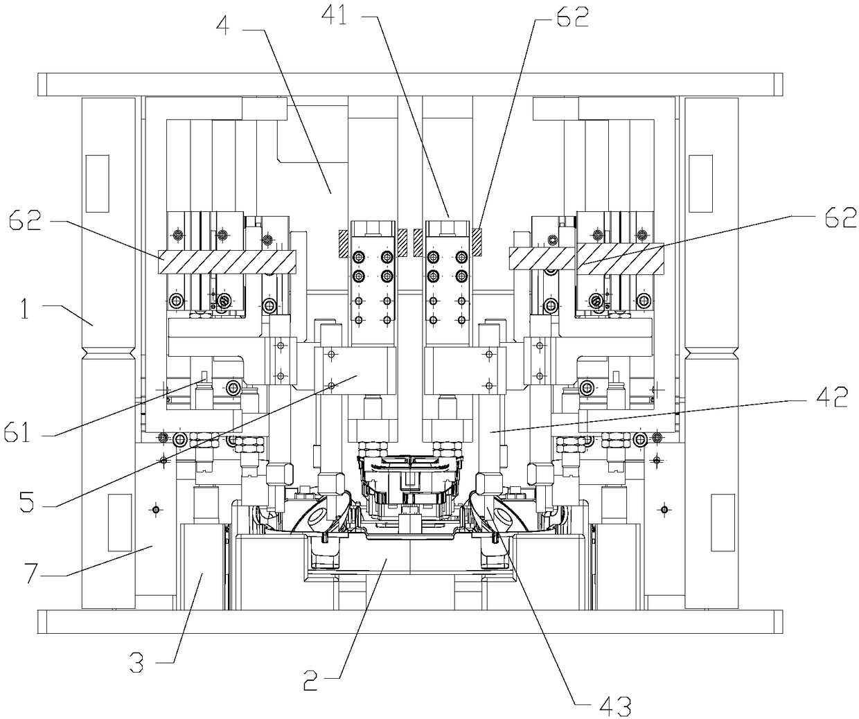
[0018] Such as figure 2 As shown, this embodiment and figure 1 The differences in the shown methods are: first, the heating tubes 42 of the six groups of hot riveting processing units 4 are respectively movably connected with the corresponding connecting blocks 5 . In this way, each group of heating tubes 42 (hot riveting heads 43) can act independently, except that they can be lifted and lowered independently, and the heating tubes can also move horizontally through the movable connection with the connecting block 5, so that In the case that the workpiece switch is complicated or the size of the workpiece at different riveting points is different, in addition to adjusting the up and down distance of the hot riveting head relative to the riveting point, the position of the corresponding workpiece riveting point under the hot riveting head can also be adjusted to ensure The riveting effect of the riveting points at the workpieces of different shapes and sizes at different pos...


PUM


Abstract

The invention relates to the field of machining devices, in particular to a hot riveting machining device adopting a hot riveting machining process. The device comprises a machine frame. A workbench provided with clamping air cylinders used for fastening machining parts is fixed to the lower portion of the machine frame. At least two sets of hot riveting machining units which are each composed ofa hot riveting air cylinder, a heating pipe and a hot riveting head are arranged on the part, above the workbench, of the machine frame correspondingly, and limiting devices for limiting movement of the hot riveting air cylinders are further arranged on the machine frame. The hot riveting machining device has the advantages that the hot riveting temperature, time and positions can be adjusted andcontrolled, and thus the workpiece riveting effect and efficiency are improved.

Description

technical field [0001] The invention relates to the field of mechanical processing devices, in particular to a device for hot riveting processing of plastic parts such as lamps and lanterns by using a hot riveting processing technology. Background technique [0002] With the development of the economy, my country's auto industry is developing faster and faster, and the auto lamp industry as auto parts has also entered a period of rapid growth. As an important process in the assembly of headlights, hot riveting technology is also being used more and more. The tooling of the existing hot riveting processing equipment is processed from a whole piece of metal, and the riveting is heated by a built-in heating tube in the tooling. The position adjustment of the tooling in this type of equipment is only achieved by rising and falling and only through one master cylinder. Since the hot riveting tooling is processed as a whole, multiple riveting points need to be riveted. If the wel...

Claims


Application Information

Patent Timeline
Patent Type & Authority Applications(China)
IPC IPC(8): B29C65/20B29C65/78B29L31/30
CPCB29C65/20B29C65/7841B29L2031/30B29L2031/747
Inventor 罗云飞
Owner JIANGSU YEDI AUTOMOTIVE LIGHTING SYST
Learn More